

Complete IEC 62305 lightning protection guide covering risk assessment (Part 2), LPS classes I-IV, rolling sphere method, down conductors, air termination, and SPD selection. We offer a complete, integrated capability to provide lightning protection solutions for towers, antennas, and other structures. Our products can. – Lightning attraction effect and power supply mode of communication towers – Sensitivity of equipment – Economic benefits Definition and statistics of lightning strike intensity Thunderstorm Day Nk: Nk < 25 days – low risk area Nk > 25 days – medium risk area Nk > 40 days – high-risk area Nk > 90. This case study analyzes a 220 kV–400 kV substation connection using 36 power transmission towers, 2. With this in mind, LEC has created a solution which makes it easy to implement a complete lightning. Recommendation ITU-T K. The need of protection is obtained from the methodology contained in IEC 62305-2, which is used to determine the relevant lightning protection. Investing in proper lightning and surge protection for communications infrastructure can avoid these risks and disruptions.
[PDF Version]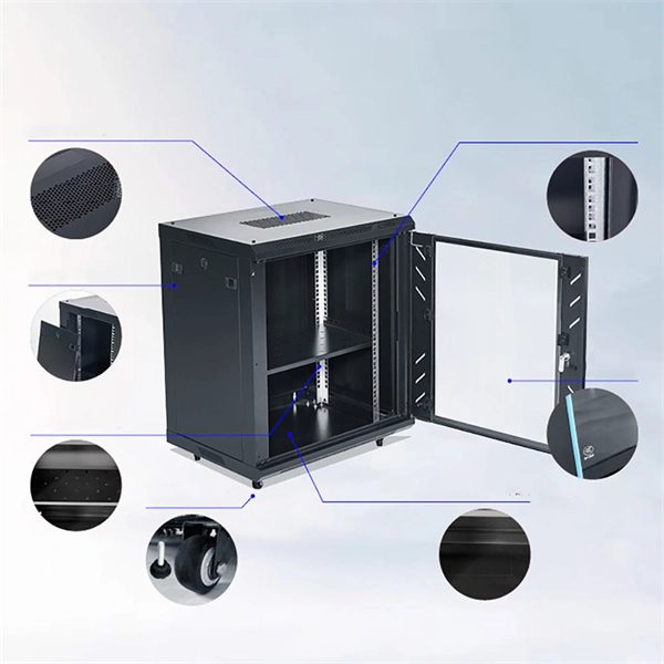
This guide covers essential NEC Article 250 requirements for industrial facilities, OSHA grounding standards and compliance strategies, and practical testing and maintenance procedures that ensure your grounding system performs when it matters most. Whether you're designing a new facility, upgrading existing infrastructure, or ensuring ongoing compliance, mastering industrial electrical grounding requirements protects your workforce, prevents costly downtime, and keeps your operation running safely. Circuits are grounded to limit excessive voltage from lightning, transient surges, and unintentional contact with higher voltage lines, and to limit the voltage to ground during normal operation. It can also be an aid to all engineers responsible for the.
The TFT (Thin-Film Transistor) screens used in relay protection applications play a pivotal role in providing operators with clear, actionable information in real-time. Its modular design and powerful DIGSI 5 engineering tool provide tailored solutions. This reference design showcases a two-dimensional (2-D) Qt graphical user interface (GUI), which is typical for. presentation of protection and control relaying. The report will identify methodology behind these practices, present issues raised by the integration of microprocessor relays and the internal logic and external communication configurations, ying. The first numerical relays were released in 1985.
The article provides an overview of protective relaying principles and their applications for high-voltage power system components. It covers the protection methods for generators, transformers, buses, and transmission lines using various relay types to detect and isolate faults efficiently.
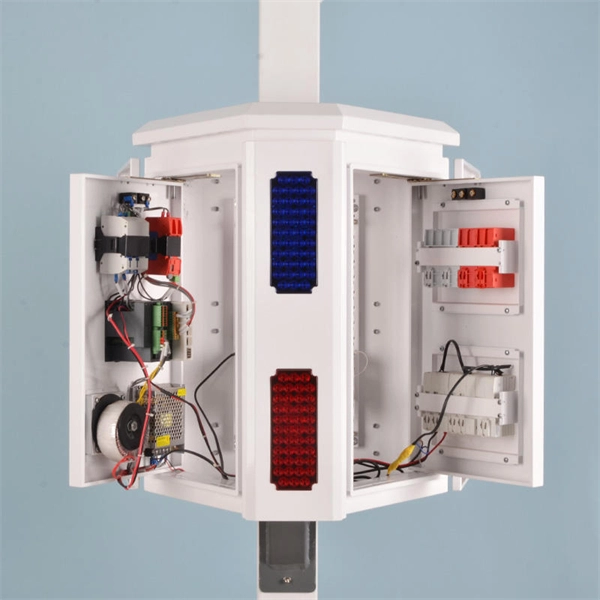
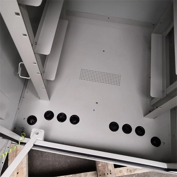
The metal box of the distribution box, the electrical installation board, and the metal base and casing of the electrical appliances in the box must be grounded. The protective neutral wire should be reliably connected through the terminal board. Are you expecting any of those 6 switches will require a neutral connection? @RobertChapin Does not. But it does require panelboard with a neutral that has more than 10 percent of its overcurrent devices rated 30 amperes or less to be protected against overcurrent by a device that has a rating not greater than that of the panelboard. It includes isolator, RCCB (Residual current circuit breaker) or RCD (Residual-current device) devices, protective fuses or MCB's (Miniature Circuit Breaker).
It is generally installed in the socket circuit of each household distribution box and the power supply line of the whole building distribution box, the latter is dedicated to prevent electrical fire. Leakage protection is leakage maintenance. After the human body contacts the leakage, it will take the initiative to disconnect and maintain the. Selecting and installing the right protective enclosure ensures long-term electrical safety in demanding environments. A robust waterproof distribution box shields sensitive components from moisture, dust, and mechanical impacts. This guide primarily analyzes structural engineering characteristics. - **Power inlet connection**: Generally, a leakage protector has two inlet terminals, marked as L (live wire) and N (neutral wire). When wiring, make sure the stripped length of the wire is.
Electromechanical protective relays operate by either, or. Unlike switching type electromechanical with fixed and usually ill-defined operating voltage thresholds and operating times, protective relays have well-established, selectable, and adjustable time and current (or other operating parameter) operating characteristics. Protection relays may use arrays of, shaded-pole, magnets, operating and restraint coils, solenoid-type operators, telephone-relay contacts.
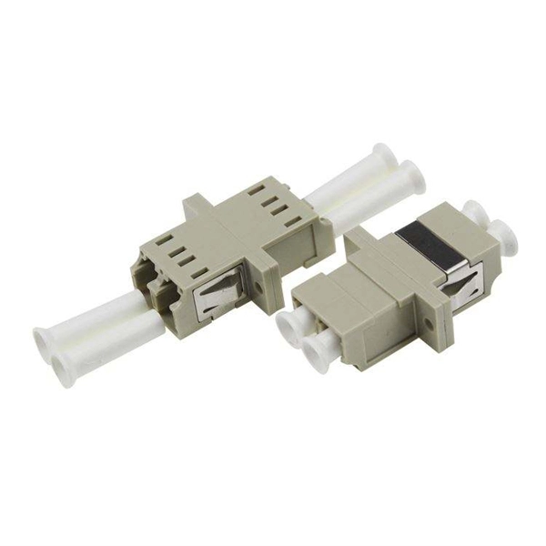
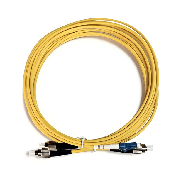
Polyethylene (PE) is the material of choice for use as an aerial OSP cable jacket. The performance of raw PE can degrade rapidly through exposure to sunlight but the addition of carbon black to the cable jacket absorbs the UV light to protect the plastic jacket of the cable. Fiber optic cables enable high-speed, long-distance data transfer, forming the backbone of modern communication. Yet, outdoors, they face temperature swings, moisture, UV exposure, rodents, and human interference. This guide covers how to. Deploying fiber above ground on poles or towers removes the need for underground digging and is particularly useful when the ground is uneven, rocky or both. Some are self-supporting, requiring no separate messenger wire between poles to support the cable's weight. As the leading world manufacturer of fiber optic cable, AFL is uniquely positioned to provide a full line of. Aerial work mixes mechanical engineering (span, sag, tension), careful selection of cable types (ADSS, figure-8, lashed) and a disciplined safety-first attitude.
[PDF Version]
The IEC 61439-1 sets the thermal limit in busbars working at the maximum working load. Here, 140°C (which is 105K over the ambient temperature of 35°C) is the upper safe temperature limit. Continuous, real-time busbar temperature monitoring and hot spot detection for MV & HV switchgear, substations and power plants — EMI-immune, calibration-free, fully SCADA-integrated. Thermal monitoring locations include: Eaton Exertherm CTM solution for MV switchgear. Standards mandate that busbars, when carrying their rated continuous current for extended periods, must not experience excessive temperature rise.
Guidance on settings for the 132kV system is given in CP338, and for the 33kV and 11/6. Relay protection is essential to ensure the stability, reliability, and safety of electrical power systems. Protective relaying is the backbone of fault detection and system isolation in As transmission systems grow increasingly complex with integration of. This document states the Electricity North West Limited policy for protection for all high voltage systems. It covers standard codes, wiring practices, and norms for protecting generators, transformers, and lines, and provides detailed. Abstract: Covered in this recommended practice is the protection of bus and switchgear used in industrial and commercial power systems. Protection selectivity is partly considered in this report and could be also re-evaluated.
Contact us for competitive quotes on any of our power communication and smart grid products
Get a Quote