
Protective circuit functional testing, including lockout relay testing, must take place immediately upon installation, every 2 years thereafter, and upon any change in wiring. THEY SHOULD BE GIVEN FIRST LINE MAINTENANCE ATTENTION. ” relay may only need to operate for 0. But failure to operate as intended can result in extensive damage, extended power outages, and loss of life. NETA. The testing and verification of relay protection devices can be divided into four groups: Type tests are needed to prove that a protection relay meets the claimed specification and follows all relevant standards. Acceptance tests fall into two categories : (i) On new relays which are to be used for the first time. Features: Durable with no moving parts, ideal for modern grids.
A straightforward way of obtaining selective protection is to use time grading. The principle is to grade the operating times of the relays in such a way that the relay closest to the fault spot operates first. Calculate pickup values, timing curves, coordination time intervals (CTI), and test injection currents for overcurrent (50/51), differential (87), distance (21), and directional (67) protective relays. Accurately measuring the action time is a crucial step to ensure the reliability and. For successful protection coordination, relay working times must be accurately calculated since overcurrent relays activate when circuit current exceeds a predetermined threshold limit. The free online Time Overcurrent Relay Calculator lets electrical engineers immediately calculate relay operate. This calculator evaluates time-current coordination between two protective overcurrent relays — typically a downstream relay closer to the load and an upstream relay closer to the source — at a specified fault current level.
[PDF Version]
This is a test to check the maximum length of time that the protection relay can withstand an interruption in the auxiliary supply without de-energizing, e. switching off, and that when this time is surpassed and it does transiently switch off, that no maloperation happens. Since the basic function of a protection relay is to correctly function under abnormal. Verify instantaneous pickup setting for motor protection relay blocks motor starting current but clears high-level faults Relay calibration drift causes cascading failures: a relay set to operate in 0. 8 seconds allows fault damage to propagate upstream, tripping feeder. Megger's smart relay testing solutions and expert support help you validate protection performance, improve system reliability, and ensure continuity of power across your network.
The NetTest CMA4000 is an advanced OTDR (Optical Time Domain Reflectometer), designed for fiber optic network testing. The CMA4000 Optical Test System is an all-in-one test and measurement solution for network commissioning, fault location/restoration, maintenance, and DWDM spectral analysis. It provides high-resolution measurements, extensive analysis capabilities, and is ideal for troubleshooting optical networks. Here's a link to NetTest_CMA4000_Spec_Sheet. Memory upgrades, color screens, power meter, VFL and software update options available. They characterise the len th, attenuation and return loss (ov se individual events along ink: connection points (splices, connectors), te ng by particles much smaller than the wavelength of the.
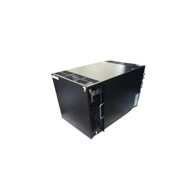
In one of Australia's most remote regions, NEXTDC and Vertiv partnered to deliver PH1 Port Hedland — a modular, edge data centre bringing cloud connectivity and resilience to the Pilbara area. Utilising EcoStruxure™ IT, LEDC monitors all facilities in real time, remotely, ensuring uptime across their network of connected Tier 3 data centres. Innovative IT and data centre solutions that. Click Learn More to View the Case Study. LEDC Cloud Services Providing Private Cloud Infrastructure, Backup and Storage Services to Regional Australia. “It's begun! Work on NextDC's GE1 4. 4MW data center in Geelong has commenced, bringing new capability to the region,” Adam Gardner, head of Edge at NextDC, said on LinkedIn this week.
OTDRs display trace results by plotting reflected and backscattered light versus distance along the fiber, characterizing any reflective and non-reflective events in a fiber link. These reflections, known as Fresnel reflections, are meticulously measured by the OTDR to pinpoint the location of these events within the fiber link. Due to the inherent structure of the fiber and microscopic imperfections within the glass, a small portion of the light pulse scatters in various. An optical time-domain reflectometer (OTDR) is an optoelectronic instrument used to characterize an optical fiber. The OTDR is also commonly used to create a "picture" of fiber optic cable when it is newly installed. However, its value lies not only in taking measurements but also in correctly interpreting the records (traces) it generates.
Contact us for competitive quotes on any of our power communication and smart grid products
Get a Quote