
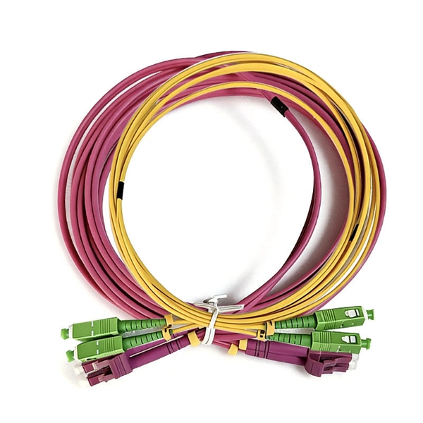
The fiber latency calculator helps determine the time it takes for data to travel through a fiber optic cable between two points. This. Calculate round-trip time, propagation delay, and understand network latency components. 792 meters per microsecond (µs) or 3. In fiber optics, the. Fiber optic cables revolutionized global communications, enabling high-speed data transfer over long distances with minimal signal loss. The light is a form of carrier wave that is modulated to carry information.
If damage is found, contact your supplier immediately. Verify that all components listed in the packing slip are present. Before initial use, fully charge the device's internal battery. Connect the provided AC power adapter to the power input port on the device (refer to Figure 3. The EXFO MAX-730D-SM8 is a high-performance Optical Time Domain Reflectometer (OTDR) designed for comprehensive fiber optic network characterization and troubleshooting. No part of this publication may be reproduced, stored in a retrieval system or transmitted in any form, be it electronically, mechanically, or by any other means such as photocopying, recording or otherwise, without the prior writt eved to be accurate and reliable. Ensure that the ambient temperature in the location where you charge the batteries is within the specifications (the battery. The MaxTester 700B/C Series is the first tablet-inspired OTDR line that is handy, lightweight and rugged enough for any outside plant environment. The OTDR is a valuable tool for anyone who works with optical fibers.
[PDF Version]
Below 180mA, according to the working principle of optical module, normal 1. However, with the increasing use of time limit, many of the old module operating current will be. SFP (Small Form-factor Pluggable) optical modules are compact, hot-pluggable transceivers that enable network equipment to connect seamlessly to fiber and copper links. These modules, including SFP, SFP+, and SFP28, are widely used in enterprise networks, data centers, and carrier-grade deployments. The optical power output of an SFP module refers to the amount of light power that the module can transmit over a fiber optic link. This is typically measured in dBm (decibels relative to one milliwatt) and is a crucial factor in determining the reach and quality of the optical signal. It transforms high volumes of electrical signals into optical signals for transmission. This guide provides average transmit and receive power ranges for transceiver modules.
[PDF Version]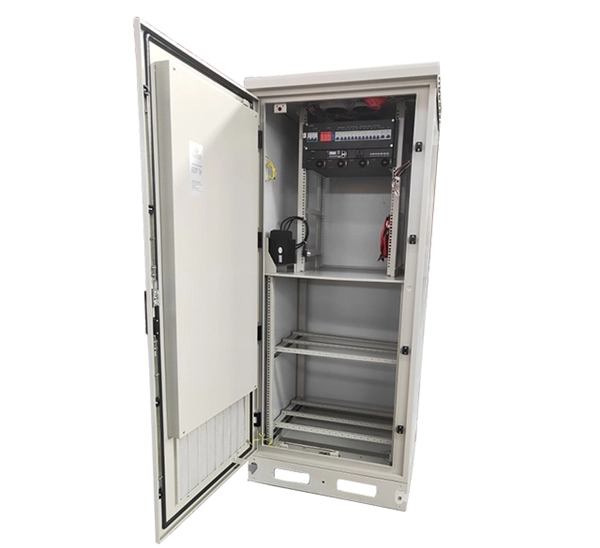
Although the field and currents are shown in one direction, they actually reverse direction with the alternating current in the transformer winding. Eddy currents generate resistive losses that transform some forms of energy, such as kinetic energy, into heat.OverviewIn, an eddy current (also called Foucault's current) is a loop of induced within by a changing in the conductor according to or by the relative. The term eddy current comes from analogous currents seen in in, causing localised areas of turbulence known as giving rise to persistent vortices. Somewhat analogously, eddy curre. The first person to observe eddy currents was (1786–1853), the President of the Council of Ministers of the 2nd French Republic during the brief period from 10 May to 24 June 1848 (equivalent to the current.
The first experiments in were conducted by beginning in 1894. In 1895–1896 he invented the, which was initially a wire suspended from a tall wooden pole. He found that the higher the antenna was suspended, the further he could transmit, the first recognition of the need for height in antennas. Radio began to be used commercially for.
The FTB-500 can house any of EXFO's FTB plug-and-play modules, enabling you to reconfigure your test solution as your test needs evolve. Combine physical and optical characterization applications with transport and datacom test modules covering next-generation 10G, 40G and 100G. Fiber OTDR FTB-1 /FTB-500 Optical Time Domain Reflectometer otd price EXFO FTB-1-720 Optical Loss Test Set / Used OTDR Machine / Fiber Inspection Microscope FTB-1 OTDR 1. We locate in Beijing- the capital of China. Right out of multi-application wonderland. More than 15 years professional. Chinese, English, Spanish,Portuguese. We locate in Beijing- the capital. The FTB-500 platform embodies a completely new approach to work: more advanced applications, faster setup, testing and reporting, wireless communication and universal compatibility with all FTB modules from the company EXFO – old, current and future. So go ahead: break new grounds, set new test-performance standards, and tame new technologies. Benefit from an all-in-one platform that you can build around your most.
[PDF Version]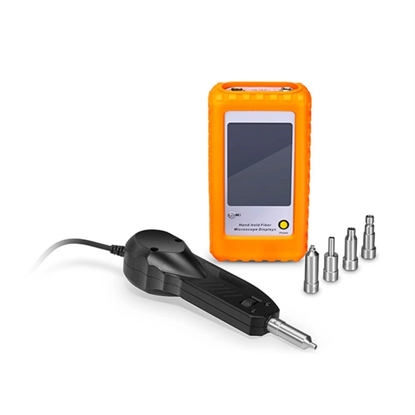
The document discusses various multiplexing techniques, including frequency division multiplexing (FDM), time division multiplexing (TDM), wavelength division multiplexing (WDM), and code division multiplexing (CDM). Multiplexing in data communications is a method that combines multiple signals or data streams into one signal over a shared medium. This process allows for efficient use of resources and can significantly increase the amount of data that can be sent over a network.
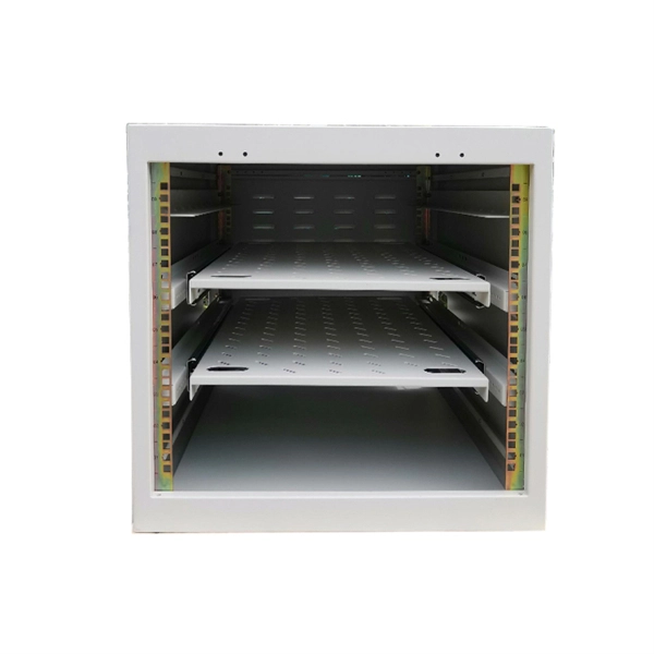
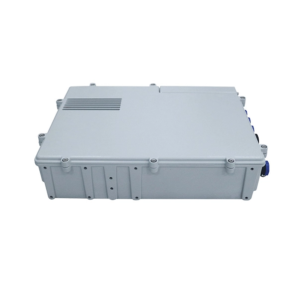
For most packages, the processing time at a distribution center is between 24-48 hours. During this time, the package is sorted, scanned, and dispatched to a carrier for delivery. However, this timeframe can vary depending on the factors mentioned above, such as shipping method. The manufacturing process focuses on precisely assembling these elements into a safe, reliable, and long-lasting unit. It all begins with raw materials. Most enclosures are made from sheet steel, galvanized steel (for corrosion resistance), or specially rated plastic composites. Modern distribution and fulfillment centers serve as the operational heart of the supply chain, where goods are received, stored. Packages end up there after a missed delivery attempt, a hold request, or a redirect, and the process is straightforward once you know where to go and what to bring. For LTL and FTL shipments, it can take up to 10 days.
[PDF Version]Contact us for competitive quotes on any of our power communication and smart grid products
Get a Quote