
This is a test to check the maximum length of time that the protection relay can withstand an interruption in the auxiliary supply without de-energizing, e. switching off, and that when this time is surpassed and it does transiently switch off, that no maloperation happens. Since the basic function of a protection relay is to correctly function under abnormal. Verify instantaneous pickup setting for motor protection relay blocks motor starting current but clears high-level faults Relay calibration drift causes cascading failures: a relay set to operate in 0. 8 seconds allows fault damage to propagate upstream, tripping feeder. Megger's smart relay testing solutions and expert support help you validate protection performance, improve system reliability, and ensure continuity of power across your network.
Testing a splitter or other passive fiber optic devices like switches is little different from testing a patchcord or cable plant using the two industry standard tests, OFSTP-14 for double-ended loss (connectors on both ends) or FOTP-171 for single-ended testing. A passive device used to split or combine signals on fiber optics may be called a splitter, combiner or coupler, but splitter is the most common term. 6inch color touch screen, button/touch dual operation; Internal integration of eight major functional modules, multi-functional. As fiber deployments become commonplace, network owners and technicians are paying more attention to the two crucial devices for testing fiber optical cables: the Optical Loss Test Set (OLTS) and the Optical Time Domain Reflectometer (OTDR). An OLTS provides the most accurate insertion loss. The CertiFiber® Pro Optical Loss Test Set (OLTS) can be used to check that the loss of a PON Splitter (often referred to in various standards as a non-wavelength-selective or wavelength-selective branching device) to check that it is within the allowed defined limits. To view the full specifications, download the spec sheet below.
[PDF Version]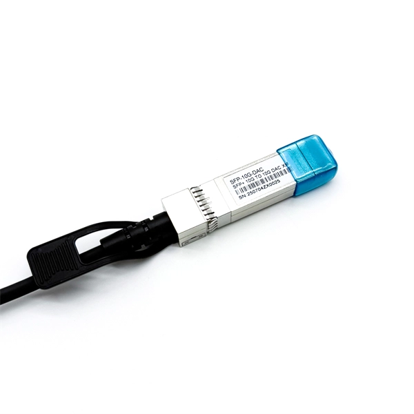
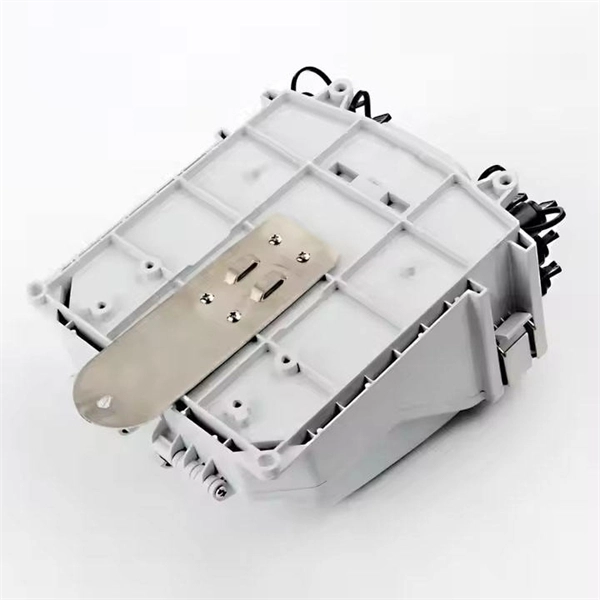
A relay protection tester is a device used to test and verify the performance of relay protection devices in power systems. This happens because the main function of protection devices is related to operation under fault conditions so these devices cannot be tested under normal operating conditions. Megger's smart relay testing solutions and expert support help you validate protection performance, improve system reliability, and ensure continuity of power across your network. Ensure protection systems operate correctly. The main function of a protection relay is to detect primary-sided faults or overloads as rapidly as possible and to selectively isolate the affected assets or parts of the grid from the rest of the grid or substation using circuit breakers.
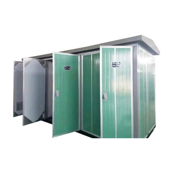
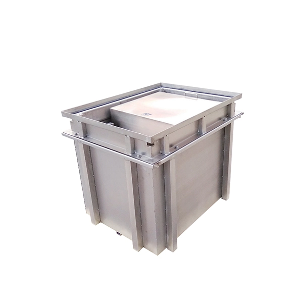
The following is extracted from a paper on ESS testing prepared by the U.S. Air Force to provide standardized definitions and methods. Introduction The purpose of this paper is to provide standardized definitions and a roadmap of test processes for the Environmental Stress Screening (ESS) of replacement and repaired components used on Air Force systems. The term “component” is use. SummaryEnvironmental stress screening (ESS) refers to the process of exposing a newly manufactured or repaired product or component (typically ) to stresses such as and in order to force late. Developed to help electronics manufacturers detect and production flaws, ESS is widely used in military and aerospace applications, less so for commercial products. The tests need not be elab. Tailoring is the formal engineering task of using existing technical data (requirements, standards, specifications, test plans, etc.) and selecting or modifying applicable areas to meet the requirements unique to the type of unit unde.
[PDF Version]
Connect a visible light source (such as a fiber optic flashlight) to one end of the cable. Take an LED flashlight and shine the light into one of the fiber. The three standard methods for testing fiber optic cabling are a visible light source, power meter and light source, and optical time domain reflectometer (OTDR). Because fiber optic transmissions work in the infrared portion. FiberLert is a fast, accurate, and safe non-contact solution for verifying fiber activity, polarity, and connectivity. First, aim your smartphone camera at the connector; most phone sensors detect the otherwise invisible 85.
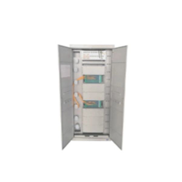
The IEC has published a new standard for the testing of fibre optic cabling. IEC 61280-4-5 provides test methods to measure the attenuation of installed multimode and single-mode optical fibre cabling plant as well as the determination of their polarity and length. Fiber optic testing of a newly installed system not only verifies that the system meets its design requirements, but also creates a performance baseline for all future testing and troubleshooting of t at system. Corning recommends that all fiber optic systems be tested to a minimum set. for installing electrical products and systems. NEIS® are intended to be referenced in contrac documents for electrical construction ation or liability to users of this publication. Lower attenuation means less signal loss over distance. Patch cords and jumper cables must meet stricter performance requirements because connectors. ANSI/TIA‑568.
[PDF Version]
The R1+R2 method links the line conductor and circuit protective conductor (CPC) at the consumer unit and measures the combined resistance at the furthest point of the circuit — typically at the last socket outlet. The tests described below are carried out, documented, analysed and evaluated there. DIN EN 60670-1, VDE 0606-1 This standard applies for sockets, housings and housing parts for electrical. It is designed to assess the operational status of network connections, identifying issues in signal strength, interference, and connectivity. This category encompasses a variety of testing tools, including network cable testers, Ethernet test devices, and more specialized equipment like cable. Proper testing and inspection of resistors are essential to ensure the reliability and functionality of electronic devices. Record building and cabinet identifiers, room and keyholder details, power setup, PDU capacity and spare ports, UPS equipment, and switch makes, models, ports, and identifiers. To effectively test an Ethernet port with a multimeter, it's crucial to understand the basics of Ethernet cabling and how a.
[PDF Version]
Here's a basic guide on how to measure ground resistance and test the grounding system's proper functionality using a multimeter: According to NEC 250. If you're setting up a server rack, one of the most important things to consider is proper server rack grounding. Without it, you risk electrical shock, equipment. Bonding (or grounding) is a system of protective measures, which is implemented to prevent electric shocks when touching metal parts of energy-powered equipment. The whole structure consists of a metal circuit, a protect bus, and a ground wire. 1100, TIA-942, how to apply the information found in. How to Check Earthing and Measure Ground Resistance using a Multimeter? Measuring ground resistance using a multimeter is generally not as accurate as using specialized ground resistance testers, but it can provide a rough estimate. A properly grounded rack mitigates the risks associated with electrostatic discharge (ESD), transient voltage surges, and fault currents.
[PDF Version]Not grounding a grounded rack can result in various risks, including electrostatic discharge (ESD) that can damage sensitive electronic components,...
To determine if your server rack is properly grounded, you can use an electrical multimeter to measure resistance between the rack's ground connect...
When connecting servers and equipment to a grounded rack, ensure that grounding cables are not overly stretched or under strain, avoid daisy-chaini...
Yes, there are different grounding methods for server racks. These methods include using grounding bars, grounding strips, and direct grounding cab...
There are industry standards and regulations for server rack grounding, often set by international and regional bodies. In the U.S., for instance,...
Power meter testing will be conducted at both wavelengths (if under 64 km) and only at 1550nm for spans greater than 64 km. The term usually refers to a device used for measuring the average power in fiber optic systems. Other general purpose light power measuring devices are usually called radiometers, photometers, laser power. While optical power meters are the primary power measurement instrument, optical loss test sets (OLTSs) and optical time domain reflectometers (OTDRs) also measure power in testing loss. Consistent procedures ensure accuracy. Verify light travels from. OWL manufactures a complete line of fiber optic test equipment for a wide range of applications, including telco, WAN, MAN, LAN, SAN, CATV, IT, manufacturing, and laboratory. OWL's complete line of fiber optic testers have capabilities ranging from simple optical power and optical loss measurement. An optical power meter (OPM) measures the power levels of light signals in devices that transmit data or power using light.
[PDF Version]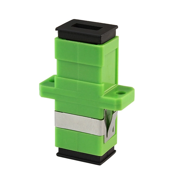
The full-link automatic test platform of the relay protection fault information system includes three parts: the main station remote test module, the sub-station test management module and the autom.
Contact us for competitive quotes on any of our power communication and smart grid products
Get a Quote