
Arc-shaped cable trays are cable trays with an arc-shaped structure. Adaptable to curved cabling: They perfectly fit curved shapes in circular buildings, stadiums, theaters, and other locations, making cable laying smoother and avoiding cable stress caused by right-angle bends. en completely installed, without damage either to conductors or structural system use maintain spacing or to keep cables in place when the tray is ect the minimum bend ra-dius for cables as they exit the bottom of the cable tray. Eaton's submittal builder tool. Most projects are roughly defined at the start of cable tray design. For projects that are not 100 percent defined before design start, the cost of and time used in coping with continuous changes during the engineering and drafting design phases will be substantially less for cable tray wiring. Hubbell's NEXTFRAME® Ladder Tray is the effective and widely used cable runway that supports and delivers bundles of cable between cabinets, racks, and closets, along walls, and suspended from ceilings. We use different types of trays for different jobs: Ladder.
[PDF Version]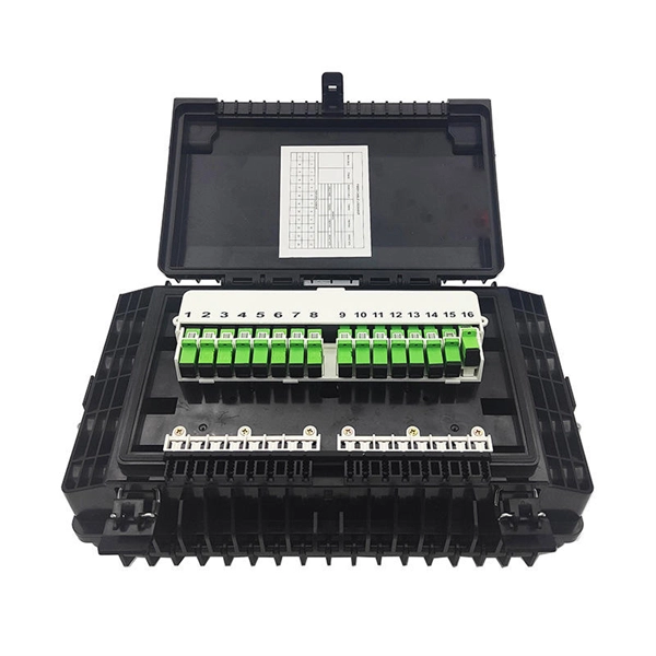
Our engineer's guide helps you choose the right outdoor cable tray based on environment, load, and corrosion resistance. Select HDG, Aluminum, or FRP with confidence. An outdoor cable tray represents a sophisticated infrastructure solution designed to organize, protect, and route electrical cables in external environments. Installed on ceilings, walls, or floors, these trays ensure safe cable routing while protecting against.
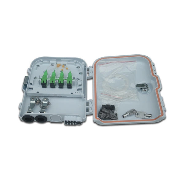
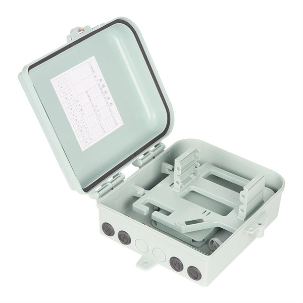
Optical cable tray is a system designed to protect and route fiber optic patch cords, cable assemblies to and from network cabinets, ODF and other terminal devices. Ducting offers ideal solutions for optical raceway requirements and application with pleasing appearance and easy. Cable trays are frequently used for both power and communications cables in industrial applications. Its basic components include: straight grooves, horizontal and vertical elbows, optical fiber outlets, connectors and supports.
A modern cable tray production line typically consists of several key components that work in unison to ensure efficiency and quality. The primary stages of the production process include raw material handling, cutting, forming, welding, finishing, and quality assurance. Cable trays are crucial for organizing cables, keeping them safe from physical damage, and ensuring their proper functioning over time. Understanding the. As a crucial component of power and electrical engineering, cable trays have complex production processes involving multiple stages. The production process of cable trays, from design to finished product, usually includes the following key steps: Design and Planning Stage The production process of. The production process of cable trays can be divided into six core stages. You'll witness how a coil of metal strip is transformed into standardized, ready-to-install cable trays.
[PDF Version]
EAE cable trays and ladders provide high-strength cable protection that protects the cables from external factors. The standard tray length is 3m. 6m can be produced upon request. Our experienced teams and operations are present across the Middle-East North Africa regions (MENA) and Pakistan, giving us. A Middle East and Africa (MEA) cable tray is a support system designed to hold, organize, and protect electrical cables in various infrastructure projects across the region. Made from materials such as steel, aluminum, or fiberglass, these trays form a pathway for electrical wiring in commercial. Tired of messy wires causing headaches? Brilltech Engineers Pvt. Cables are used to provide a rigid structural system for electrical cables, raceways, and insulated conductors used for electric power distribution, control, signal instrumentation, and communication. Based on materials used in the Fabrication.
[PDF Version]
Metal actually expands and contracts with weather change, and leaving some small gap in between tray sections is a must. When the distance between the metals is too low, the metals will push against each other and bend. VE 1 Figure 6-9 is a nomograph from which the required metal expansion. For step-by-step method on how to determine the maximum spacing between expansion joints and splice gap settings, refer to the following steps: Step 1: Identify the maximum and minimum temperature at the project site and calculate the (∆) temperature differential. A rung spacing of 6 to 9 inches (150 to 230 mm) is preferable when the cable tray cont d for instrumentation and control applications that require.
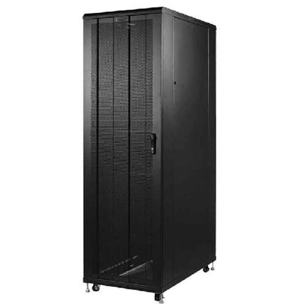
The perforated U steel cable tray is a specialized product developed for the computer rooms and stations of telecommunications operators such as China Telecom, China Mobile, China Unicom, China Netcom and China Railcom. Cable tray may be used as the Equipment Grounding Conductor (EGC) in any installation where qualified persons will service the installed cable tray system. It not only serves the purpose of cable management but also supports the weight. us-trations without notice. The mechanical and electrical characteristics, tests, certifications, overall quality management, recommendations mentioned. en completely installed, without damage either to conductors or structural system use maintain spacing or to keep cables in place when the tray is ect the minimum bend ra-dius for cables as they exit the bottom of the cable tray. Cable ladder systems and cable tray systems shall be manufactured in accordance with BS EN 61537, channel support. This method statement covers the site installation of the cable tray & ladders and the requirements of checks to be carried out. This section will guide you through the necessary steps to ensure a successful.
[PDF Version]
Enter cable details, get the recommended tray width instantly — with a print-ready engineering report, revision block, and full EULA included. Built specifically for electrical and instrumentation. Our free calculator helps you determine the correct tray size based on NEC and IEC standards. Follow these simple steps: Define Tray Dimensions: Enter the width and depth of your planned cable tray (in mm or inches). This calculator features an interactive interface with advanced visualizations. Save your cable tray sizing calculator results as branded PDF. Cable tray size calculation is important for ensuring safe cable installation, proper heat dissipation, and enough spare capacity for future expansion. Cable management is the unsung hero of modern infrastructure.
The bends, tees, crosses, risers and reducers of wire mesh cable tray can be easily and quickly made live at the project by using a bolt cutter. Since the jaws of the bolt cutter drags a layer of zinc across the cut end and forms a protective layer. Students trading aid on how best to put an internal 90 degrees bend in steel cable tray. WhatsApp:17802216114Email:bernice@hx-machinery. When a wire cable tray is cut, the fact that a. maintain spacing or to keep cables in place when the tray is ect the minimum bend ra-dius for cables as they exit the bottom of the cable tray. A rung spacing of 6 to 9 inches (150 to 230 mm) is preferable when the cable tray cont d for instrumentation and control applications that require. This document deals with cables trays, cables and connector installation and segregation, cable trays earthing and E. These rules shall be applied in the cabling engineering workflow for all subjects concerning or in relationship with cabling in the ITER facility.
[PDF Version]Contact us for competitive quotes on any of our power communication and smart grid products
Get a Quote