
The key problems are related to low fault current and low inertia and affect directional and distance elements, faulted-phase identification, and remote backup protection. We have three ways to tackle the rising protection challenges: fine-tune the present protective relays, enforce a better fault response of the sources, and use protection principles that are less dependent on the sources. The paper also introduces a new. Abstract—Transmission line protective relays are assuring normal operation of power system by automatically isolating faulted sections. This paper explores various aspect. The loadability limits and requirements on transmission lines can introduce additional constraints for protective relaying, as protection must be able to allow the transmission line to be temporarily overloaded while still retaining the ability to correctly detect and clear faults. Engineering use: Protection engineers use distance, differential, directional overcurrent, pilot, and backup schemes to. This paper is about the effects of protective relaying on the loadability of transmission lines.
[PDF Version]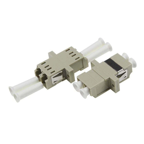
The TFT (Thin-Film Transistor) screens used in relay protection applications play a pivotal role in providing operators with clear, actionable information in real-time. Its modular design and powerful DIGSI 5 engineering tool provide tailored solutions. This reference design showcases a two-dimensional (2-D) Qt graphical user interface (GUI), which is typical for. presentation of protection and control relaying. The report will identify methodology behind these practices, present issues raised by the integration of microprocessor relays and the internal logic and external communication configurations, ying. The first numerical relays were released in 1985.

Remove the CPU module from the relay housing and set aside. Be certain to align the printed circuit board with the card guides in the housing. Always use antistatic bags for transporting modules Remove AC power and DC power from the PCD before removing, installing or wiring any of the PCD modules. Consult. What are the steps for safely removing and reinstalling a PLC CPU module? Safe removal and reinstallation of a PLC CPU module requires strict adherence to proper procedures to prevent equipment damage, data loss, or safety hazards. Consult the most recent PCD Instruction Book for details on programming the new CPU to suit your requirements. 0 or Modbus ASCII communications, protocol documentation is available. 1. 1 INTRODUCTION TO THE UR The GE Universal Relay (UR) series is a new generation of digital, modular, and multifunction equipment that is easily incorporated into automation systems, at both the station and enterprise levels. In particu-lar, one will find: General information with regard to design, configuration, and operation of SIPROTEC 4 devices are set out in the SIPROTEC 4 System Description /1/.
[PDF Version]
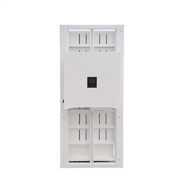
It is generally installed in the socket circuit of each household distribution box and the power supply line of the whole building distribution box, the latter is dedicated to prevent electrical fire. Leakage protection is leakage maintenance. After the human body contacts the leakage, it will take the initiative to disconnect and maintain the. Selecting and installing the right protective enclosure ensures long-term electrical safety in demanding environments. A robust waterproof distribution box shields sensitive components from moisture, dust, and mechanical impacts. This guide primarily analyzes structural engineering characteristics. - **Power inlet connection**: Generally, a leakage protector has two inlet terminals, marked as L (live wire) and N (neutral wire). When wiring, make sure the stripped length of the wire is.

This article explores the current trends, innovations, and market insights surrounding relay protection, focusing on tools like the secondary injection test set, three-phase relay test set, and single-phase relay test set. able sources such as wind and solar. These clean energy sources, connected through inverters and flexible transmission systems, are transforming traditional grids based on synchronous generators into more flexibl cant challenges to system stability. A big difference between conventional electromechanical and static relays is how the relays are wired. Numeric. IEEE/IAS/I&CPSD Protection & Coordination WG Chair Jacobs Canada, Calgary, AB rasheek. com IEEE Southern Alberta Section PES/IAS Joint Chapter Technical Seminar - November 2016 Protective Relays - Technical Seminar Nov 2016 - Copyright: IEEE 2 Abstract: Protective relays and devices. At the core of a modern substation lies the protection relay: an intelligent electronic device (IED) that plays a critical role in maintaining the stability of the power grid by continuously monitoring voltage, current, frequency, and phase angle.
[PDF Version]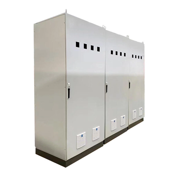
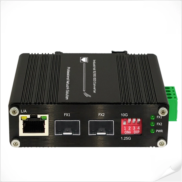
A power over ethernet surge protector, also known as a PoE surge protector (Surge Protective Device), is designed to protect Ethernet-based systems from transient overvoltage caused by lightning activity, switching operations, or electrical disturbances in nearby equipment. It is widely used in IP-based systems such as IP cameras, wireless access points, and network switches, where both. By sending data and electrical power over a single cable, PoE simplifies installations and powers devices such as IP cameras, wireless access points and VoIP phones. But with great convenience comes vulnerability. Protect your network devices from lightning strikes and ESD. It, therefore, requires special. This article is the first in the "Protect Your Ports! Top Design Tips to Keep Your Communications Connected" series from Littelfuse. It's now widely used in both everyday and industrial settings.
[PDF Version]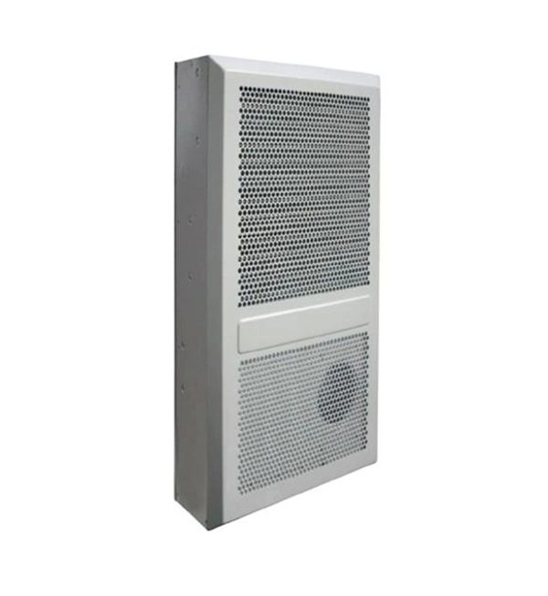
This leakage current is measured in milliamps 'mA' (1/1000 amp) and if the leakage current reaches a pre-determined level, usually 30 mA '0. 03 A' the device will operate and isolate the supply from the circuit. In addition to fault protection (protection in cases of indirect contact), residual current protective devices with rated residual currents up to 30 mA also provide “additional protection” in cases of direct contact. Fires caused by ground-fault currents can also be prevented at a very early stage. Subsequently, new types of RCD have been developed. This article. RCDs, or Residual Current Devices, are designed to monitor the electrical current flowing in a circuit and automatically disconnect the power supply if it detects an imbalance between the live and neutral conductors.
Electromechanical protective relays operate by either, or. Unlike switching type electromechanical with fixed and usually ill-defined operating voltage thresholds and operating times, protective relays have well-established, selectable, and adjustable time and current (or other operating parameter) operating characteristics. Protection relays may use arrays of, shaded-pole, magnets, operating and restraint coils, solenoid-type operators, telephone-relay contacts.
Distance relays, also known as impedance relay, differ in principle from other forms of protection in that their performance is not governed by the magnitude of the current or voltage in the protected circuit but rather on the ratio of these two quantities.OverviewIn, a protective relay is a device designed to trip a when a is detected. The. Electromechanical protective relays operate by either, or. Unlike switching type electromechanical with fixed and usually ill-defined operating voltage thresholds. Electromechanical relays can be classified into several different types as follows: "Armature"-type relays have a pivoted lever supported on a hinge or knife-edge pivot, which carries a moving contact. These relays may.
Contact us for competitive quotes on any of our power communication and smart grid products
Get a Quote