

In electric power distribution, a busbar (also bus bar) is a metallic strip or bar, typically housed inside switchgear, panel boards, and busway enclosures for local high current power distribution, transmission, or switching substations. They are also used to connect high voltage equipment at electrical switchyards, and low-voltage equipment in battery banks. They are generally uninsulated, and h. Design and placementThe busbar's material composition and cross-sectional size determine the maximum current it can safely carry. Busbars can have a cross-sectional area of as little as 10 square millimetres (0.016 sq in), but. • – Data transfer channel connecting parts of a computer• – Low resistance electrical conductor for high current transmission and distribution• – Modular approach t. • Elmore, Walter A. (1994). Protective Relaying Theory and Applications. Marcel Dekker.• Paschal, John (2000-10-01). Electrical Construction & Maintenanc.
[PDF Version]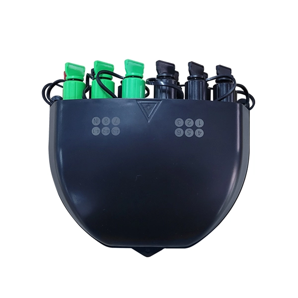
Switched Rack PDUs enable advanced, customizable power control and active monitoring for datacenter and edge environments. The Liebert® RXV remote power distribution cabinet provides dense power distribution in a small footprint, with up to 400 Amp inputs and 84 poles in a single 24”x12” panelboard. It offers both a Mul-colour OLED. IPDM intelligent precision cabinet is composed of the power distribution system, lightning arrester, computer-grade grounding compartment, and power monitoring system. Whether that means speeding up Saturday installs or focusing on. ABB offers a total ev charging solution from compact, high quality AC wall boxes, reliable DC fast charging stations with robust connectivity, to innovative on-demand electric bus charging systems, we deploy infrastructure that meet the needs of the next generation of smarter mobility.
Over voltage protection relays detect when the current's voltage exceeds a preset value. The entire system will shut down. It prevents safety hazards and damage to equipment. Many industries use voltage protection relay systems, especially those in high-voltage. Relays designed for voltage protection are fundamental in today's electrical systems as they help in mitigating equipment damages and also prevent infrastructural breakdowns arising from voltage anomalies. It continuously measures voltage levels within electrical systems, and if it recognises a voltage problem that might. Protective Relay Definition: A protective relay is an automatic device that senses abnormal conditions in electrical circuits and triggers actions to isolate faults. It works by monitoring incoming power and disconnecting the circuit if the voltage becomes too high or too low.
Learn the correct sequence: LV off before HV, control before main, and never operate isolators under load. Power Off and Power On Sequence in the Distribution Room When de-energizing, first disconnect the low-voltage (LV) side, then the high-voltage (HV) side. First open all LV branch circuit breakers, then open the LV main breaker. When an overload or short circuit occurs, the breaker rapidly interrupts the flow of electricity, preventing conductors from overheating and potentially starting a. Phase 3's Powersafe Sequential Mating Box controls the connection sequence of incoming / outgoing high current cable connections. With key (included) turn the Earth lock clockwise. These switches are responsible for protecting the electrical circuits from overloads and short circuits. By referring to the wiring diagram, you can easily identify which circuit. Connection method: Each switch takes a wire from the incoming point and connects it to the incoming end of the switch, or uses parallel connection to reduce the difficulty of wiring.
[PDF Version]
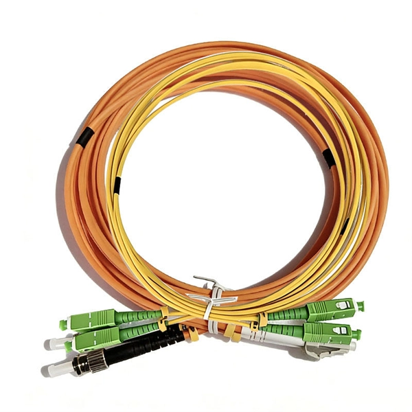
What is an Optical Switch Module? An optical switch module is an optical device featuring one or more selectable transmission ports, designed to physically switch or logically manipulate optical signals within an optical transmission line or an integrated optical circuit. Thorlabs' offers a selection of optical switches. Also available are. Optical switching is the process of controlling the destination of individual optical information signals. Figure: Optical Switch. POLATIS ® Series 6000 Optical Switch Modules (OSM) are high-performance, fully non-blocking all-optical matrix switch modules with port counts from 16xCC up to 48xCC, offering "any-to-any" port connectivity. 2 dB), fastest switching speed (10 ns), broadest wavelength range (300–2400 nm), widest fiber compatibility, highest optical power handling (50 W), and space-qualified reliability.
This article explains how to power up more PoE devices (PDs), what's the difference between 802. 3at mode as well as the difference between classification and consumption mode in Power over ethernet on your switch . PoE: Power over Ethernet (PoE) is a technology that allows Ethernet cables to carry electrical power, along with data, to powered devices. The initial allocation for Class 0, Class 3, and Class 4 powered devices is 15. This allows a single cable to provide both a data connection and enough electricity to power networked devices such as wireless access points. When working with your network devices, it's important to understand each device's power requirements and the types of Power over Ethernet (PoE) they support. Power is passed from Power Sourcing Equipment (PSE) over the twisted pairs to Powered Devices (PD) such as IP phones, IP cameras, card.
Contact us for competitive quotes on any of our power communication and smart grid products
Get a Quote