
The FC/PC (Physical Contact) and FC/APC (Angled Physical Contact) connectors are standardized under TIA EIA/TIA-604-4 and IEC 61754-13. For APC Connectors, understanding the difference between step and conical ferrules is crucial for proper polishing. This comprehensive comparison analyzes the relevant IEC standards for E2000, LC and SC fibre optic connectors and shows their specific areas of application. FC connectors are used in datacom, telecommunications, measurement. IEC fiber connector standards establish the global specifications for connector geometry, mating interfaces, optical performance classes, and mechanical testing across all fiber network environments. These standards ensure that passive fiber-optic components remain interoperable, stable, and. The FC connector is a fiber optic connector with a screw thread locking mechanism to withstand high-vibration environments Radiall's FC connector is composed of a plated nickel housing and a 2. 5 mm ceramic ferrule and is compliant with the CEI 61754-13 standard. They are widely used in ODF, ODN,PON etc.
[PDF Version]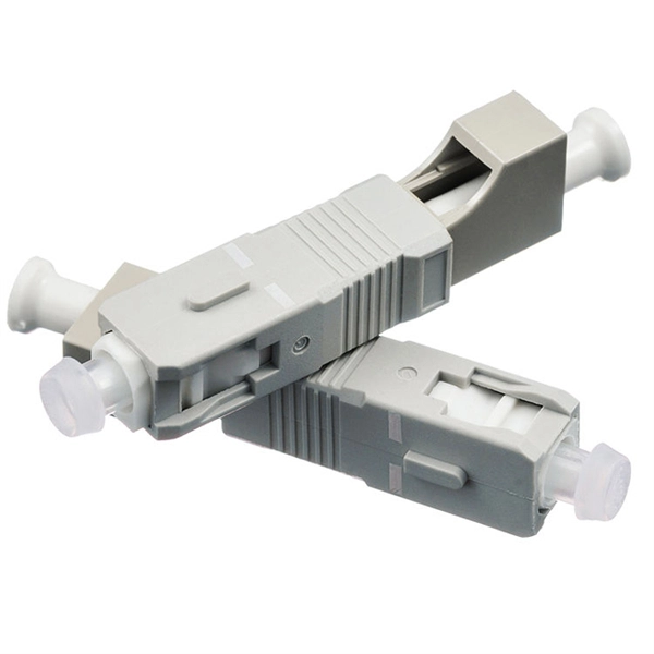
Ceramic ferrules are essential elements in fiber-optic connectors. They hold the end of an optical fiber in place while precisely aligning it to its socket of the connector – without them, power may be lost during transmission. They are made of zirconia ceramic, which offers the highest performance and durability of all ferrule material types. Ceramic injection molding (CIM) technology is used to meet high precision requirements. Granulated nano-zirconia powder raw materials are granulated and then. Ceramic ferrules are mainly used in the precise physical connection of optical fiber cores in the field of optical communication,and are a core component of optical communication connectors. Rosen offer various shapes of ceramic ferrules.
Install fiber optic connections rapidly with this field-installable fast connector designed for FTTH and outdoor applications. The arrays are manufactured using precision silicon wafer V-Groove technology or Pyrex V-Groove in conjunction with a Pyrex lid, enabling sub-micron alignment accuracy with UV cure attachment capabilities. The FITEL Ninja is a powerful, fully-automatic, state-of-the-art V-groove splicer. It is suited for metro, LAN, and fiber-to-the-home applications and can be used in a variety of applications. This high-quality. The PM V-Groove arrays are mass produced to be incorporated in various photonic devices, particularly for high speed 40 Gb/s to next generation 100 Gb/s coherent detection systems. Robust Stainless Steel - Optical fiber V groove crafted from industrial-grade stainless steel maintains. Corning offers a suite of cost-effective glass V-grooves and arrays that are pitched at 127 microns and 250 microns, with product configurations ranging from 1 to 96 channels.
[PDF Version]
Use SC/APC (green) where return loss matters most—outdoor drops, PON splitters, ONTs—thanks to its typical RL ≥ 60 dB. Never mate APC with UPC; always match polish to. Fiber optic connectors are devices used to terminate the end of an optical fiber and enable quicker connection and disconnection than splicing. Designed to split one optical signal into two, the 1×2 PLC splitter is indispensable for network engineers and telecom providers building. My ISP has configured the fiber cable to the router using a blue connector. you must have matching connectors. Most PON systems using UPC (blue) are EPON. Manan Enterprises - Offering Fiber Plc Splitter With Connector Blue/green Sc&apc & Cassatte Type 1x8, Packaging Size: Small, Size: Standard at ₹ 325/piece in Mumbai, Maharashtra. Whenever you pass the signal from a blue color (SC-PC) to green (SC-APC) or vice-versa you lose between 3dBm.
[PDF Version]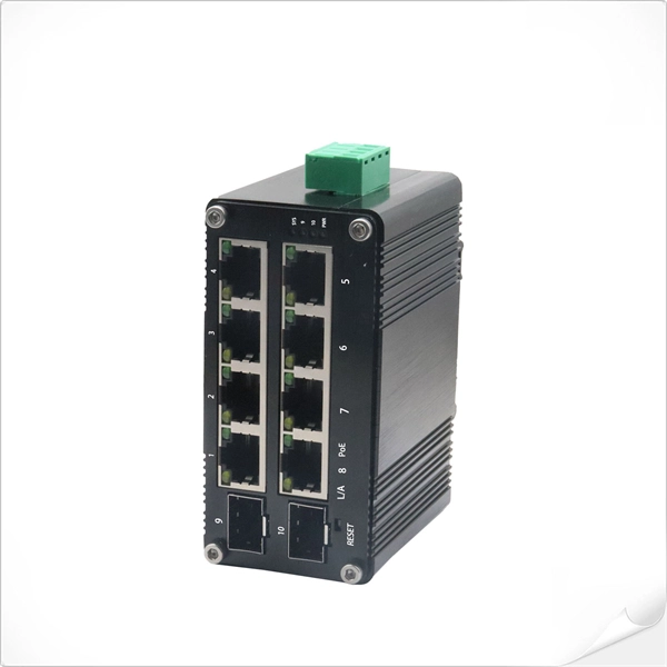
A fiber optic adapter, also known as a fiber coupler, is a passive device used to connect and align two optical fiber connectors. It enables optical signals to pass from one fiber to another with minimal loss, ensuring stable and reliable communication. LC, MU, SMA connectors with round or square type press button.
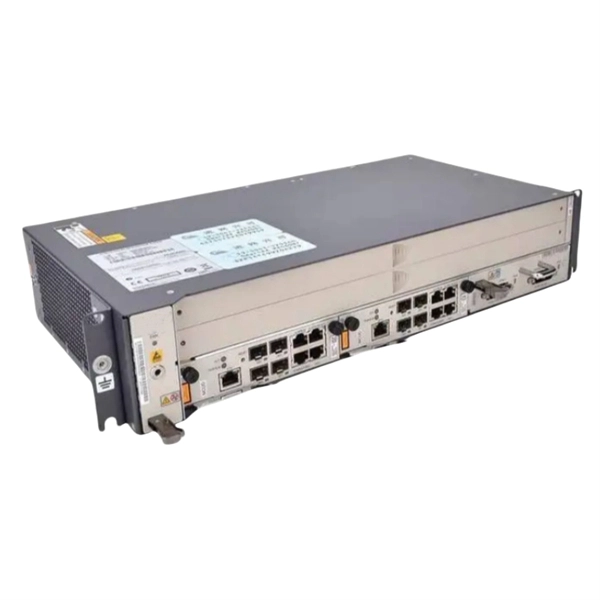
The BIX Distribution Connector is a 25-pair connector. The connector's symmetrical construction allows termination of cables on one side and cross-connect jumper wires or BIX Patch Cords on the other. As mentioned before, a jumper is a conductor that is used to connect two or more points in an electrical circuit. Comprehensive accessories such as switching jumpers or. Ready to install in panel boxes, switches, outlets, and other devices, these cords come with a spade terminal already attached to one end.
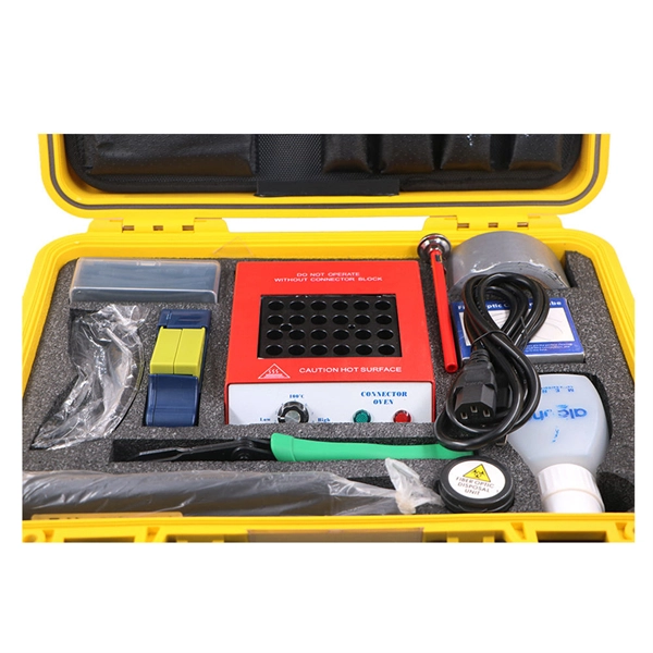
Use launch cable to measure the first connector of the link. Increase pulse width for more dynamic range. OTDR settings are a balance between dynamic range, acquisition time, spatial resolution and accuracy. To minimize testing time, compromises must be made on accuracy (detecting low loss. OTDR (Optical Time Domain Reflectometer) testing is a vital technique for characterizing and troubleshooting optical fiber networks. It provides valuable information about fiber length, loss, and the location of events like splices and connectors. However, like any measurement technique, OTDR. An OTDR works by transmitting high-power light pulses into the fiber and measuring the light reflected from any event or the end of the fiber due to a change in the refractive index. But you may wonder, "How can I use an OTDR to locate splice loss and connector issues?" The answer is simple, with the right OTDR, you can pinpoint problem areas along the fibre.
[PDF Version]Contact us for competitive quotes on any of our power communication and smart grid products
Get a Quote