
A straightforward way of obtaining selective protection is to use time grading. The principle is to grade the operating times of the relays in such a way that the relay closest to the fault spot operates first. Calculate pickup values, timing curves, coordination time intervals (CTI), and test injection currents for overcurrent (50/51), differential (87), distance (21), and directional (67) protective relays. Accurately measuring the action time is a crucial step to ensure the reliability and. For successful protection coordination, relay working times must be accurately calculated since overcurrent relays activate when circuit current exceeds a predetermined threshold limit. The free online Time Overcurrent Relay Calculator lets electrical engineers immediately calculate relay operate. This calculator evaluates time-current coordination between two protective overcurrent relays — typically a downstream relay closer to the load and an upstream relay closer to the source — at a specified fault current level.
[PDF Version]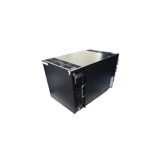
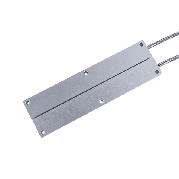
Protective circuit functional testing, including lockout relay testing, must take place immediately upon installation, every 2 years thereafter, and upon any change in wiring. THEY SHOULD BE GIVEN FIRST LINE MAINTENANCE ATTENTION. ” relay may only need to operate for 0. But failure to operate as intended can result in extensive damage, extended power outages, and loss of life. NETA. The testing and verification of relay protection devices can be divided into four groups: Type tests are needed to prove that a protection relay meets the claimed specification and follows all relevant standards. Acceptance tests fall into two categories : (i) On new relays which are to be used for the first time. Features: Durable with no moving parts, ideal for modern grids.
If damage is found, contact your supplier immediately. Verify that all components listed in the packing slip are present. Before initial use, fully charge the device's internal battery. Connect the provided AC power adapter to the power input port on the device (refer to Figure 3. The EXFO MAX-730D-SM8 is a high-performance Optical Time Domain Reflectometer (OTDR) designed for comprehensive fiber optic network characterization and troubleshooting. No part of this publication may be reproduced, stored in a retrieval system or transmitted in any form, be it electronically, mechanically, or by any other means such as photocopying, recording or otherwise, without the prior writt eved to be accurate and reliable. Ensure that the ambient temperature in the location where you charge the batteries is within the specifications (the battery. The MaxTester 700B/C Series is the first tablet-inspired OTDR line that is handy, lightweight and rugged enough for any outside plant environment. The OTDR is a valuable tool for anyone who works with optical fibers.
[PDF Version]
This is a test to check the maximum length of time that the protection relay can withstand an interruption in the auxiliary supply without de-energizing, e. switching off, and that when this time is surpassed and it does transiently switch off, that no maloperation happens. Since the basic function of a protection relay is to correctly function under abnormal. Verify instantaneous pickup setting for motor protection relay blocks motor starting current but clears high-level faults Relay calibration drift causes cascading failures: a relay set to operate in 0. 8 seconds allows fault damage to propagate upstream, tripping feeder. Megger's smart relay testing solutions and expert support help you validate protection performance, improve system reliability, and ensure continuity of power across your network.
The first experiments in were conducted by beginning in 1894. In 1895–1896 he invented the, which was initially a wire suspended from a tall wooden pole. He found that the higher the antenna was suspended, the further he could transmit, the first recognition of the need for height in antennas. Radio began to be used commercially for.
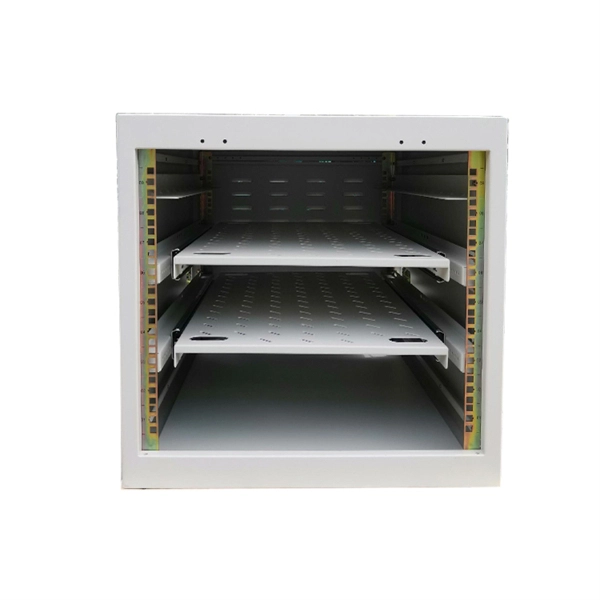
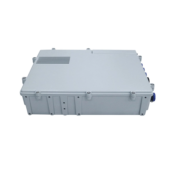
For most packages, the processing time at a distribution center is between 24-48 hours. During this time, the package is sorted, scanned, and dispatched to a carrier for delivery. However, this timeframe can vary depending on the factors mentioned above, such as shipping method. The manufacturing process focuses on precisely assembling these elements into a safe, reliable, and long-lasting unit. It all begins with raw materials. Most enclosures are made from sheet steel, galvanized steel (for corrosion resistance), or specially rated plastic composites. Modern distribution and fulfillment centers serve as the operational heart of the supply chain, where goods are received, stored. Packages end up there after a missed delivery attempt, a hold request, or a redirect, and the process is straightforward once you know where to go and what to bring. For LTL and FTL shipments, it can take up to 10 days.
[PDF Version]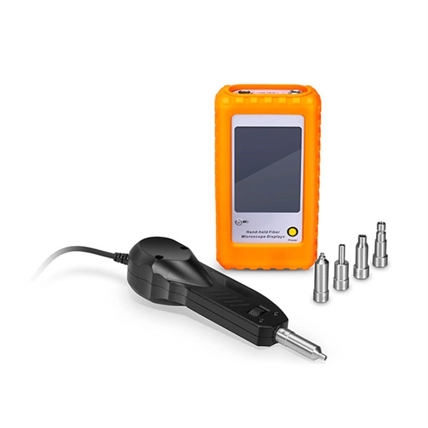
The document discusses various multiplexing techniques, including frequency division multiplexing (FDM), time division multiplexing (TDM), wavelength division multiplexing (WDM), and code division multiplexing (CDM). Multiplexing in data communications is a method that combines multiple signals or data streams into one signal over a shared medium. This process allows for efficient use of resources and can significantly increase the amount of data that can be sent over a network.
Contact us for competitive quotes on any of our power communication and smart grid products
Get a Quote