
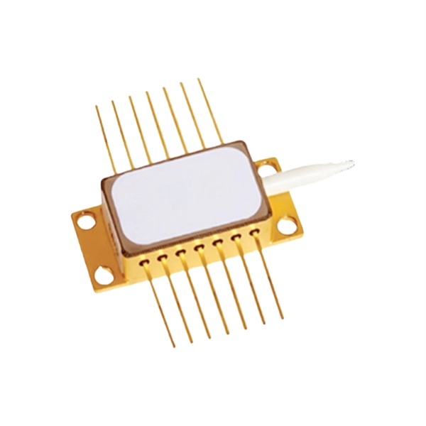
Silicon photonics has developed into a mainstream technology driven by advances in optical communications. The current generation has led to a proliferation of integrated photonic devices from t.
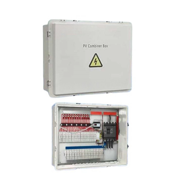
This AutoCAD DWG file includes a complete Single Line Diagram (SLD) of a Distribution Board, showing circuit breakers, wiring connections, and load distribution for lighting, power, and mechanical systems. Indication Lights: These provide visual availability and status of mains power supply. Each component plays a specific role. Together, they make sure the electrical power distribution box works well and safely. Smart DB boxes have extra parts like energy monitoring units and communication modules. In practical applications, the corresponding system diagram can be drawn. PROVIDE SERVICE LOOP FOR ALL HORIZONTAL VOICE, DATA, AND VIDEO CABLES NOT TO EXCEED 10 FEET. LOCATION TO BE DETERMINED BY THE RUPM. PROVIDE (3) 30A SPARE CIRCUITS IN ELECTRIC PANEL. 3/4" AC FIRERATED PLYWOOD ON ALL WALLS, PAINTED WITH WHITE FIRE RETARDANT PAINT (DO NOT PAINT PLYWOOD LABEL). MOUNT. The ArTu distribution switchboards are enriched by the new L series for applications up to 630A, which widens the ABB offer in the secondary and terminal distribution sector: a series able to combine quality performances with maximum selection and assembly simplicity.
[PDF Version]
This AutoCAD DWG file includes a complete Single Line Diagram (SLD) of a Distribution Board, showing circuit breakers, wiring connections, and load distribution for lighting, power, and mechanical systems. Indication Lights: These provide visual availability and status of mains power supply. Each component plays a specific role. Together, they make sure the electrical power distribution box works well and safely. Smart DB boxes have extra parts like energy monitoring units and communication modules.
In, an eye pattern, also known as an eye diagram, is an display in which a from a receiver is repetitively sampled and applied to the vertical input (y-axis), while the data rate is used to trigger the horizontal sweep (x-axis). It is so called because, for several types of coding, the pattern looks like a series of eyes between a pair of rails. It is a tool for the evaluation of the combi.
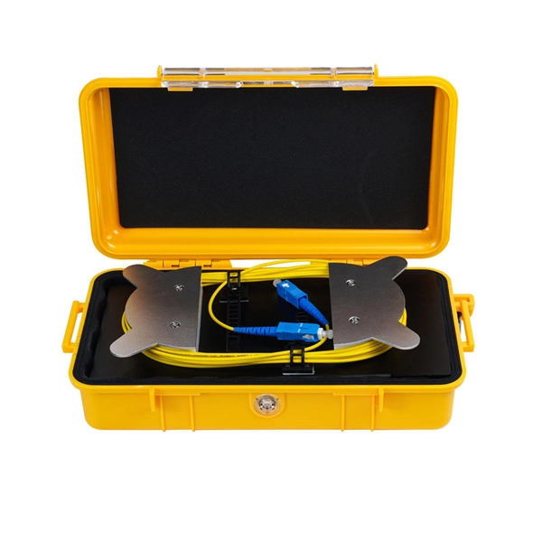
Single Mode Fiber Optic Cable Source A single-mode fiber optic cableis a commonly used fiber optic cable used for long-distance transmission. This cable type has a small diameter core, allowing only a si.
When drawing up a single line-diagram, a great number of possible combinations of incoming and outgoing connections have to be considered. The most common ones are shown in the following di.
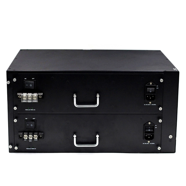
Standard high voltage connectors for voltages up to 100kV. When required, cables can be supplied terminated with HV connectors. Our PCON products include a range of high-voltage (HV) terminals specifically designed to support the increased connectivity requirements of HV interconnection systems in hybrid and all-electric vehicles. 50mm pitch with a nominal current carrying capacity of 3A.
Wiring Direction: Wiring between the main circuit breaker and each branch circuit breaker in the box generally goes on the left, and the wiring out of the distribution box generally goes on the right. Binding Requirements: The wires should be bound with plastic. Primary distribution systems consist of feeders that deliver power from distribution substations to distribution transformers. Many feeders leave substation in a concrete ducts and are routed to a nearby pole. At this. When a sizable plant expansion program is contemplated, modernization of the existing distribution system would be a necessary preparatory step. This document is not intended as a substitute for a detailed study or operational and site-specific development or schematic plan. Load factor, Coincidence factor, Contribution factor and Loss factor - Relationship between the Load factor and loss factor.
[PDF Version]Contact us for competitive quotes on any of our power communication and smart grid products
Get a Quote