
Standard reference conditions assume an ambient temperature of 30°C (86°F) for cables installed in air. When actual temperatures exceed this baseline, conductor ampacity must be reduced according to NEC Table 310. 15 (B) (1) or IEC 60364-5-52 Table B. This temperature is higher than the minimum operating temperature, and is eather, they should be kept in heated storage for at least 24 hours before instal om summer to winter, jacket movement and shrink. The minimum temperature at which a cable can be safely installed (bent, laid, or pulled) without damaging its insulation or sheath. Example: A PVC cable rated for -5°C installation temperature must not be installed in. Electrical derating is the systematic reduction of a conductor's current-carrying capacity (ampacity) to account for real-world installation conditions that deviate from standard testing environments.
Wireways and cable trays price per foot installation ranges from $8-15 for basic runs to $25-40 for complex multi-level configurations. Electrical wireways quotes rarely include all. OBO BETTERMANN has offered prod-ucts and solutions for electrical instal-lation for over 100 years. With our many years of experience, we are one of the leading manufacturers in this field. Establishing partnerships. Steel is the most widely used cable tray material due to its balance of cost-effectiveness and strength. We want to improve this website so we need your help. Please send us your recommendations, suggestion, and request. Cable ladder systems and cable tray systems shall be manufactured in accordance with BS EN 61537, channel support. This guide covers the critical steps, from selecting the right electrical cable tray and performing accurate cable fill calculations to managing a safe cable pull through and ensuring all bonding and grounding requirements are met.
[PDF Version]
This guide provides instructions for installing the H3C S6850&S9850 switch series, covering rack mounting, grounding, fan and power module installation, and expansion card setup. Table 3 Switch requirement for cleanliness To maintain cleanliness in the equipment room, follow these guidelines: · Keep the equipment room away from pollution sources. Do not smoke, eat, or drink in the equipment room. · Use double-layer glass in windows and seal doors and windows with dust-proof. Page 3 Preface H3C S5560X-HI Switch Series Installation Guide describes the appearance, installation, power-on, maintenance, and troubleshooting of the H3C S5560X-HI Switch Series. On MAN or industrial networks, it provides GE access for users and transmits the aggregated traffic from downstream switches to core switches. Field technical support and servicing engineers. The. In addition to this manual, each H3C S5600 Series Ethernet Switchesdocumentation set includes the following: Manual Description H3C S5600 Series Ethernet Switches Operation Manual It is used for assisting the users in data configurations and typical applications. H3C S5600 Series Ethernet Switches.
[PDF Version]
In hazardous areas, fibre-optic cables, especially directly inserted into flameproof chambers, are considered potentially more critical than copper wires. In this case, it is not relevant how much energy is trans.
The Trapeze or swing support is the most common type. Thread hex nut 25 mm (1") to 50 mm (2") above location of the tray bottom. The cross member comes next followed by a second set of square washers. All vertical hangers will project through the cross. This publication is intended as a practical guide for the proper and safe* installation of cable ladder systems, cable tray systems, channel support systems and associated supports. The following pages address the 2014 National Electrical Code® requirements for cable tray systems as well as design. The National Electrical Manufacturers Association (NEMA) Standards and guideline publications, of which the document herein is one, are developed through a voluntary Standards development process. This process brings together volunteers and/or seeks out the views of persons who have an interest in. We have more than a decade's worth of experience making and designing quality cable tray and cable management systems. Our knowledgeable production team works closely with each customer to provide quality solutions based on your schedule and budget.
[PDF Version]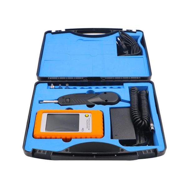
The National Electrical Code® 6'7" rule requires that devices must be readily accessible and installed so that the centerline of the overcurrent protective device operating handle, while in its highest position, is not more than 6 feet 7 inches above the floor or working platform. The proper installation of a distribution box involves placing it at the right height to ensure safety and convenience. 5 feet (≈ 2 meter) high in front of the panel. The panelboard's door (hinged cover) shall be able to be opened to a full 90°. You must make safety your top priority when working with low voltage distribution boxes. Design requirements help you follow important standards like. Installation (clearances and corridor widths) The minimum clearances between switchgear and obstacles specified by the manufacturer must be taken into account when installing low-voltage switchgear (Figure 1). The minimum dimensions for operating and servicing corridors in accordance with IEC.
[PDF Version]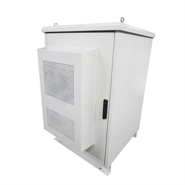
If an EGC cable is installed in or on a cable tray, it should be bonded to each or alternate cable tray sections via grounding clamps (this is not required by the NEC® but it is a desirable practice). Cable tray may be used as the Equipment Grounding Conductor (EGC) in any installation where qualified persons will service the installed cable tray system. The design must comply with relevant regulations and standards.
Contact us for competitive quotes on any of our power communication and smart grid products
Get a Quote