
A Busbar Trunking System (BTS) is a factory-built low-voltage power distribution assembly verified under IEC 61439-6. It uses prefabricated busbar sections, joints, tap-off units, and accessories to distribute power safely with defined current ratings and short-circuit withstand. Guide to Low Voltage Busbar Trunking Systems Verified to BS EN 61439-6 Introduction BEAMA is the long established and respected trade association for the electrotechnical sector. Distribution Busbar Trunking: Busbar trunking having tap-off outlets on one or more faces. It provides a modular alternative to cable risers, feeder. IEC 61439 is a standard developed by the International Electrotechnical Commission (IEC) that covers design verification for low-voltage electrical products and assemblies.
This study aims to develop a simple yet efficient performance-based design optimization methodology for cable tray systems in building structures. In the paper, the drift ratio between adjacent supports i.
Track Busway ROWs with integrated cable tray combine overhead power distribution and structured cable management in a single suspended system. This layout supports plug-in power drops while providing a dedicated pathway for data, control, or low-voltage cabling. EAE cable trays are produced on automatic production lines through the 'ROLL FORMING' method. The standard tray length is 3m. E-Line TB and E-Line URC. Busbar systems are often preferred over cables because they save space, install faster, offer greater flexibility for changes, and provide enhanced reliability, frequently leading to a lower total cost of ownership. The SIVACON 8PS BD2 system is the universal busbar for high performance within a small space—an innovative, flexible alternative. 1. Trough cable Tray adopts closed design, which can effectively prevent the cable from being damaged by external factors and ensure the service life of the cable.
[PDF Version]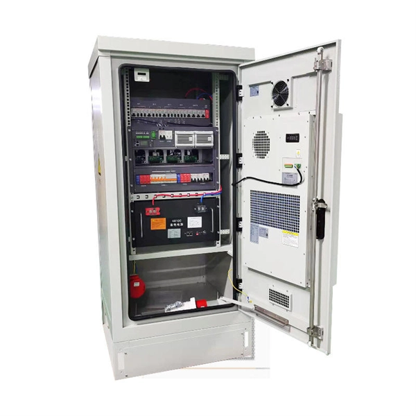
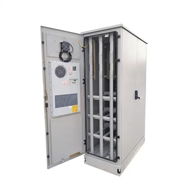
The busbar or vertical grounding strip should be used to provide a visually verifiable, all-copper grounding path. When equipment does not provide a lug-mounting pad, the next best option is to bond the equipment mounting flanges directly to the rack rails. A grounding busbar in a telecom cabinet is a conductive component used to connect all grounding points within the system. A poor layout can quietly undermine reliability and maintenance. In. To mount a bus bar to an assembly structure, hardware (studs, holes, etc. ) can be manufactured into the conductors. Mersen offers in-house conductor plating in tin. Busbar design in switchgear ensures safe, reliable power distribution by balancing current capacity, thermal performance, mechanical strength, insulation, and standards compliance.
The IEC 61439-1 sets the thermal limit in busbars working at the maximum working load. Here, 140°C (which is 105K over the ambient temperature of 35°C) is the upper safe temperature limit. Continuous, real-time busbar temperature monitoring and hot spot detection for MV & HV switchgear, substations and power plants — EMI-immune, calibration-free, fully SCADA-integrated. Thermal monitoring locations include: Eaton Exertherm CTM solution for MV switchgear. Standards mandate that busbars, when carrying their rated continuous current for extended periods, must not experience excessive temperature rise.
Guyana has a massive but yet unrealized potential for. Hydropower generation capacity has been estimated at 7,600, that is, more than 30 times the current installed capacity in the country. Feasibility studies have been carried out for specific projects, but up to now, this potential remains untapped, mainly due to the considerable capital investments required to set up new power facilities. Indeed, beside the actual investment in generation plants, transmission lines would also be r.
Bus bar grounding can be achieved by one of two methods: grounding clamps applied to bus bars or a separate switchgear section with a switching mechanism dedicated to ground. The grounding switch has short-circuit making capacity. Our earthing switch series includes different models, differing in sensor integration, pole distances, and insulating cover options, catering to diverse application needs. These. These instructions do not purport to cover all details or variations in equipment. Designed to safeguard both equipment and personnel, they provide a secure path to earth for isolated sections, ensuring residual charges are safely discharged during. The National Fire Protection Association (NFPA) 70E is a consensus standard that lays out specific steps that shall be followed in order to create “an electrically safe work condition” during electrical switchgear maintenance. First, those performing the work must understand all the possible.
[PDF Version]
In electric power distribution, a busbar (also bus bar) is a metallic strip or bar, typically housed inside switchgear, panel boards, and busway enclosures for local high current power distribution, transmission, or switching substations. They are also used to connect high voltage equipment at electrical switchyards, and low-voltage equipment in battery banks. They are generally uninsulated, and h. Design and placementThe busbar's material composition and cross-sectional size determine the maximum current it can safely carry. Busbars can have a cross-sectional area of as little as 10 square millimetres (0.016 sq in), but. • – Data transfer channel connecting parts of a computer• – Low resistance electrical conductor for high current transmission and distribution• – Modular approach t. • Elmore, Walter A. (1994). Protective Relaying Theory and Applications. Marcel Dekker.• Paschal, John (2000-10-01). Electrical Construction & Maintenanc.
[PDF Version]
Busways, or bus ducts, are long busbars with protective covers. Rather than branching from the main supply at one location, they allow new circuits to branch off anywhere along the busway.OverviewIn , a busbar (also bus bar) is a metallic strip or bar, typically housed inside,, and for local high current power distribution, transmission, or switching s. The busbar's material composition and cross-sectional size determine the maximum current it can safely carry. Busbars can have a cross-sectional area of as little as 10 square millimetres (0.016 sq in), but. • – Data transfer channel connecting parts of a computer• – Low resistance electrical conductor for high current transmission and distribution• – Modular approach t.
Contact us for competitive quotes on any of our power communication and smart grid products
Get a Quote