
In , a busbar (also bus bar) is a metallic strip or bar, typically housed inside,, and for local high current power distribution, transmission, or switching substations. They are also used to connect high voltage equipment at electrical switchyards, and low-voltage equipment in. They are generally uninsulated, and have sufficient stiffness to be s.
The IEC 61439 standard applies to busbar assemblies that will be installed in electrical applications with a voltage rating up to 1000 V (for AC) and 1500 V (for DC). 10 (not exceeding 65K or 105 degrees C for bare busbars). How do I check busbar short circuit withstand? Busbar short circuit withstand has two components: thermal and electrodynamic. Generation, transmission, distribution and control of electric energy. Electrical equipment of. The table, in addition to giving specifications regarding the maximum thickness of the busbar, the maximum current and the maximum nominal voltage, distinguishes between busbars mounted in a “Face to Face” or “Edge to Edge” arrangement. 000 40 mm bar centre distance, for Mini-PLS special busbars Rated operating voltage: up to 690 V AC Rated insulation voltage: 690 V AC Rated impulse withstand voltage: 6 kV Overvoltage category: III Pollution degree: 3 Rated frequency: 50/60 Hz Test implemented: – Rated peak. Busbar short-circuit withstand rating is expressed through three principal parameters: rated short-time withstand current (Icw), rated peak withstand current (Icp), and ultimate breaking capacity (Icu).
[PDF Version]
The process requires first to machine a dovetail ring hole and a countersunk hole in the lower and upper sheets, respectively, and then to inject a semi tubular rivet by compression through the lined-up holes to create a mechanical interlocking that can fix the two sheets in position. There are many situations where it is necessary to join two busbars to create a single, unified unit. Then we need to think about the fixing methods: All of these have many options and related pros and cons. As joints relax the resistance of that. One persistent belief is that copper busbar joints must fully overlap—matching the entire width of the bar—to ensure electrical safety and low temperature rise. However, real-world testing and. Abstract—The effect of design changes on the contact resistance of overlapping bolted/pad joints was investigated. 0 Jointing of Copper Busbars David Chapman 6.
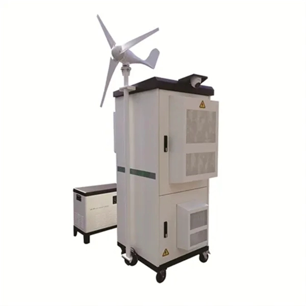
Guyana has a massive but yet unrealized potential for. Hydropower generation capacity has been estimated at 7,600, that is, more than 30 times the current installed capacity in the country. Feasibility studies have been carried out for specific projects, but up to now, this potential remains untapped, mainly due to the considerable capital investments required to set up new power facilities. Indeed, beside the actual investment in generation plants, transmission lines would also be r.
Busbar problems are often incorrectly identified as harmonic currents caused by non-linear loads. According to MET Group's field data, the primary causes of busbar and tap-off switch failures include aging, loosening connections over time, and poorly installed new systems. Fault arcs on busbar sets and switchboards Title Author Subject Fault arcs on busbar sets and switchboards-The probability of appearance of a fault arc on a set of busbars cannot be considered as non-existant. How to reduce arcing probability, limiting consequences. This generates both thermal stress (I²t heating) and mechanical stress (electrodynamic forces between conductors). Bus bar supports spacing, and bracing must be designed to withstand. switchgear busbar sizing decisions should start from voltage class, fault level, and installation environment. Clear interface data reduces site rework between transformer, switchgear, breaker, RMU, and. Additionally, busbar faults can create arc flashes, posing a major safety hazard.
[PDF Version]
In , a busbar (also bus bar) is a metallic strip or bar, typically housed inside,, and for local high current power distribution, transmission, or switching substations. They are also used to connect high voltage equipment at electrical switchyards, and low-voltage equipment in. They are generally uninsulated, and have sufficient stiffness to be s.
Contact us for competitive quotes on any of our power communication and smart grid products
Get a Quote