
In digital transmission, the number of bit errors is the number of received bits of a data stream over a communication channel that have been altered due to noise, interference, distortion or bit synchronization errors. The bit error rate (BER) is the number of bit errors per unit time. The bit error ratio (also BER) is the number of bit errors divided by the total number of transferred bits during a studied tim. ExampleAs an example, assume this transmitted bit sequence: 1 1 0 0 0 1 0 1 1 and the following. The packet error ratio (PER) is the number of incorrectly received divided by the total number of received packets. A packet is declared incorrect if at least one bit is erroneous. The expectation value of the PER is. In a communication system, the receiver side BER may be affected by transmission channel,,, problems,, wireless , etc. The BER m.
Signal-to-Noise Ratio (SNR) represents the power ratio between the desired signal and background noise, affecting the clarity of the received signal. Higher SNR values generally lead to lower BER, as stronger signals reduce the probability of error during data decoding. A high OSNR indicates a low level of noise in the system, which is critical for. The Signal-to-Noise Ratio (SNR) is a crucial metric that helps us understand the quality of signals in a system. It is defined as the ratio of the number of bits received in error to the total number of bits transmitted.
In, the number of bit errors is the number of received of a over a that have been altered due to,, or errors. The bit error rate (BER) is the number of bit errors per unit time. The bit error ratio (also BER) is the number of bit errors divided by the total number of transferred bits during a studied time interval. Bit er.
Researchers in the past have analyzed the detrimental effects of the dispersion in optical channels. However, efficient techniques of management of dispersion effects are limited, as huge data is aggregated, w.
In, the number of bit errors is the number of received of a over a that have been altered due to,, or errors. The bit error rate (BER) is the number of bit errors per unit time. The bit error ratio (also BER) is the number of bit errors divided by the total number of transferred bits during a studied time interval. Bit er.

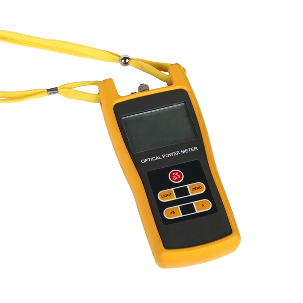
Bit Error Ratio Tester is an instrument used to test and analyze bit error ratio in digital transmission systems, fiber optic communication systems, and digital microwave communication systems. The MATRIQ BERT 1001/1005 series instruments are dual-channel or four-channel PPGs and error detectors for the development, characterization, and production of optical transceivers. Whether you are looking for the smallest handheld 100G bit error rate tester in the world for your field job, or perhaps your needs take you into the lab, VIAVI has you covered with our accurate and easy-to-use BERT equipment for any use case. The T-BERD/MTS-5800-100G handheld network tester is the. Applications for OPTELLENT's products include testing of ICs, optical components, modules (transceivers) and subsystems, networking equipment, and network installation and maintenance. OPTELLENT specializes in offering customized features on its products with short lead times. Offers precise, cost-efficient optoelectronic signal and anomaly testing for high-speed transceivers. By simulating data transmission and.
[PDF Version]
A relay protection tester is a device used to test and verify the performance of relay protection devices in power systems. This happens because the main function of protection devices is related to operation under fault conditions so these devices cannot be tested under normal operating conditions. Megger's smart relay testing solutions and expert support help you validate protection performance, improve system reliability, and ensure continuity of power across your network. Ensure protection systems operate correctly. The main function of a protection relay is to detect primary-sided faults or overloads as rapidly as possible and to selectively isolate the affected assets or parts of the grid from the rest of the grid or substation using circuit breakers.
Fiber optic cable testing can be categorized based on the type of test being conducted: End-to-End Testing: Verifies light transmission capability and signal integrity over the entire length of the cable. The performance and reliability of these networks depend on the quality of the fiber optic cables and the precision of their installation. As the components like fiber, connectors, splices, LED or laser sources, detectors and receivers are being developed, testing confirms their performance specifications and helps. This Applications Engineering Note (AEN 135) explains and recommends standard measurement methods for characterizing optical fiber system performance. A single speck of dust on a connector can cause significant signal loss.
How PI Test Works: The PI test involves applying a DC voltage to the insulator and measuring resistance at 1 minute and 10 minutes. Current Components: During the test, currents through the insulator include capacitive, conductive, surface leakage, and polarization . Polarity testing is one of the tests that are required for initial testing of the installation under IEC 60364 standard. This test will verify that all the switches installed in the system are connected in current carrying conductor and not in neutral. What Is Polarity in Electrical Installations? It refers to the direction of current flow in an. In the intricate world of electrical work, ensuring the correct polarity of alternating current (AC) is not just a matter of technical detail; it's a fundamental aspect of safety and functionality. By performing this test, you prevent electric shocks and protect sensitive equipment from damage caused by reversed wiring.
[PDF Version]Contact us for competitive quotes on any of our power communication and smart grid products
Get a Quote