
In digital transmission, the number of bit errors is the number of received bits of a data stream over a communication channel that have been altered due to noise, interference, distortion or bit synchronization errors. The bit error rate (BER) is the number of bit errors per unit time. The bit error ratio (also BER) is the number of bit errors divided by the total number of transferred bits during a studied tim. ExampleAs an example, assume this transmitted bit sequence: 1 1 0 0 0 1 0 1 1 and the following. The packet error ratio (PER) is the number of incorrectly received divided by the total number of received packets. A packet is declared incorrect if at least one bit is erroneous. The expectation value of the PER is. In a communication system, the receiver side BER may be affected by transmission channel,,, problems,, wireless , etc. The BER m.
Signal-to-Noise Ratio (SNR) represents the power ratio between the desired signal and background noise, affecting the clarity of the received signal. Higher SNR values generally lead to lower BER, as stronger signals reduce the probability of error during data decoding. A high OSNR indicates a low level of noise in the system, which is critical for. The Signal-to-Noise Ratio (SNR) is a crucial metric that helps us understand the quality of signals in a system. It is defined as the ratio of the number of bits received in error to the total number of bits transmitted.
In, the number of bit errors is the number of received of a over a that have been altered due to,, or errors. The bit error rate (BER) is the number of bit errors per unit time. The bit error ratio (also BER) is the number of bit errors divided by the total number of transferred bits during a studied time interval. Bit er.
Researchers in the past have analyzed the detrimental effects of the dispersion in optical channels. However, efficient techniques of management of dispersion effects are limited, as huge data is aggregated, w.
While major league pitchers ran a 3. 3% splitter rate in 2025, the highest mark since the pitch tracking era started in 2008, that represented a jump of just 0. It's a difference of less than one splitter per team every three games. A split-finger fastball or splitter is an off-speed pitch in baseball that initially looks like a fastball from the batters perspective, but then drops suddenly. How to well understand performance of a FBT fiber splitter and PLC optic splitters? The first important thing is to discover. Introduction: The Role of Optical Splitter in PON Network Before delving into split ratios and architectures, it's essential to ground their importance in the broader PON ecosystem. PON networks rely on passive components (no power required) to transmit data between a central OLT (located in a. Optical splitters play a crucial role in Fiber to the Home (FTTH) Passive Optical Network (PON) systems, efficiently distributing a single optical signal to multiple destinations.
[PDF Version]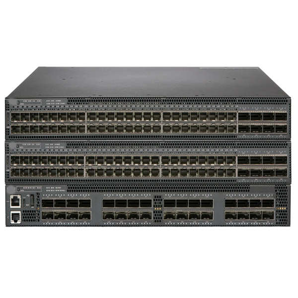
The Cable Tray Fill Calculator calculates allowable fill percentage and maximum numbers of cables, considering tray dimensions, cable sizes, spacing, and standards. Follow these simple steps: Define Tray Dimensions: Enter the width and depth of your planned cable tray (in mm or inches). Select Fill Standard: Choose 40% for power cables (NEC compliant) or 50% for. Free cable tray fill calculator for electrical designers, plant electricians, and industrial maintenance teams who need to verify that cable installations comply with NEC Article 392 fill requirements. The calculation provides necessary information to avoid cable overfilling which produces dangerous situations such as overheating, mechanical damage and reduced. Use our **Cable Tray Fill Calculator** below to size your pathways correctly *before* you buy the materials. Cable management is the unsung hero of modern infrastructure. Track counts, diameters, and weight to validate configuration quickly with live feedback. NEC Article 392 limits fill ratios based on cable type and arrangement — single-layer or stacked — to ensure adequate ventilation, maintain current-carrying capacity, and provide space.
[PDF Version]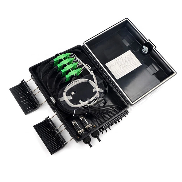
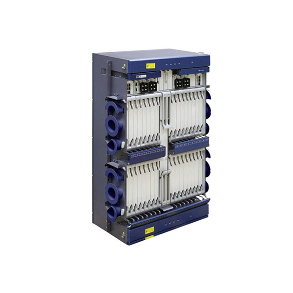
In 4G network, the optical modules used to connect BBU and RRU are mainly Gigabit to 10 Gigabit optical modules; in 5G network, the optical modules used to connect BBU and RRU are mainly 25G rate. RRU is short for remote radio unit. It also provides information about the RRU and its cables. The actual exteriors may be different. Product Versions The following table lists the product versions related to this. Can use 3. 5G rate optical module to complete the multiplexing of low-speed interface services such as 4G at a lower cost; Also used for 40KM long-distance transmission of 10G rate interface (10, 20KM for 1271nm~1371nm window). 25G SFP optical module adopts the wavelength of 850nm, with an operating. The Gamma632 is a 4G&5G dual-mode Remote Radio Unit (RRU) product independently developed by Baicells with independent intellectual property rights.
If the optical module is faulty, replace it. If the fault is caused by incorrect configuration or networking environment, change the configuration or networking environment. The working rate, duplex mode, and. Based on typical issues encountered with optical modules in daily switch applications, this document summarizes basic troubleshooting steps for resolving common faults: 1. Common Anomalies and Solutions (Quick. Customers in the use of optical modules will more or less encounter a variety of failure problems, such as optical module model selection is correct, the use of jumper is correct and some common problems, customers have the ability to judge and have a clear solution, but for some of the use of. An optical module is a critical component in modern optical communication systems, directly affecting transmission stability, network reliability, and operational efficiency. However, during installation and daily operation, various issues may arise.
[PDF Version]
The troubleshooting process typically involves three main steps: fault detection, fault analysis, and fault resolution. For example, unselective protection operation during a medium voltage network fault will cause an outage for an unnecessarily large number of consumers. Megger's smart relay testing solutions and expert support help you validate protection performance, improve system reliability, and ensure continuity of power across your network. The issue will be recorded in an internal memory.
FEC encodes outgoing data with additional bits based on well-defined mathematical rules. The receiver uses these bits to detect and correct a limited number of errors caused by impairments like dispersion, noise, or crosstalk. Block-based codes widely used in Ethernet and. By embedding redundant data that allows receivers to correct errors without retransmission, FEC delivers high-speed performance with low error rates, ensuring both scalability and cost-effectiveness. The addition contains sufficient information on the actual data to enable the FEC decoder at the receiver end to. O-FEC is an advanced forward error correction algorithm based on block turbo codes with soft-decision iterative decoding. Originally developed for the Open ROADM specifications and later adopted by the OpenZR+ Multi-Source Agreement (MSA), O-FEC provides approximately 11 to 11. That's why FEC is vital in situations where delays just aren't an option, like live video streaming, satellite links, or real-time voice calls.
[PDF Version]Contact us for competitive quotes on any of our power communication and smart grid products
Get a Quote