
Download a comprehensive set of Cable Tray Installation CAD Blocks in DWG format, ideal for electrical engineers, MEP designers, and industrial layout planners. Discover all CAD files of the "Cable trays" category from Supplier-Certified Catalogs ✅ SOLIDWORKS, Inventor, Creo, CATIA, Solid Edge, autoCAD, Revit and many more CAD software but also as STEP, STL, IGES, STL, DWG, DXF and more neutral CAD formats. Tray installation details for the location of a project's electrical wiring; in addition to blocks with different angles that allow the wiring circulation to be identified. Save time and. ABB is a leading force in the cable tray systems industry. Our lineup of aluminum, steel, stainless steel, and fiber glass cable trays and channels has been. Explore a wide array of 3D modeling and design tools to help simplify the design and specification of Legrand's various cable management systems. Several different systems and workflows are supported to make designing in your program of choice easier than before. In addition to standard programs.
[PDF Version]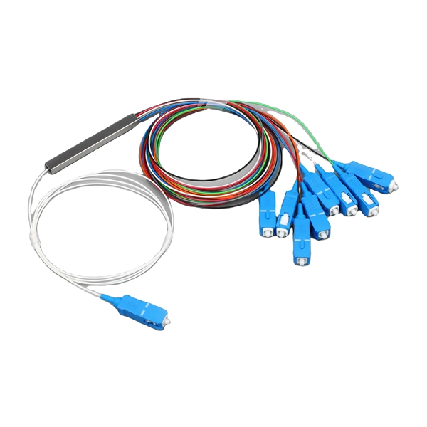
This 45 degree tray offers a 24" bend radius for ease of coax installation. Standard depth is 4" with optional depth of 6". Model numbers are 12CT45 (12" wide), 18CT45 (18" wide) and 24CT45 (24" wide). Covers and. Stainless steel 316 fitting 4 inches side rail height 9 inches width solid trough vertical inside bend 45 degree 12 inches radius For more info visit: electrification. com Made or assembled in Canada. Ensure your cable tray solution is designed for your application, with our vast range of ladder tray fittings. Choose from the following: Horizontal elbows, Vertical elbows, Tees, Reducers, Cross pieces, Branches Class 1 Tray Fittings are designed for use with NEMA Classes 12B and 12C Cable Trays. This bend provides a 45° angle bend when connecting cable tray sections. Order medium duty cable tray 45 degree flat bend (Built in Couplers) and are used to create fixed angular changes in direction in the same plane! Buy Now!Hubbell's NEXTFRAME® Ladder Tray is the effective and widely used cable runway that supports and delivers bundles of cable between cabinets, racks, and closets, along walls, and suspended from ceilings.
[PDF Version]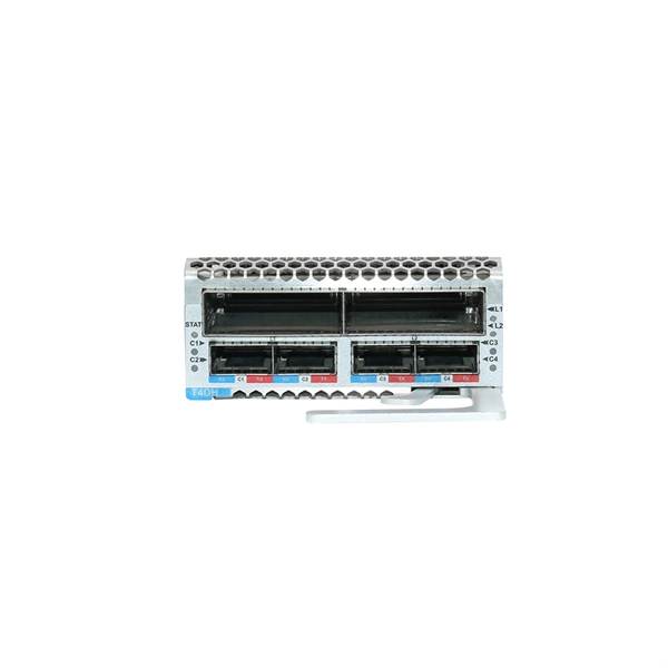
The Trapeze or swing support is the most common type. Thread hex nut 25 mm (1") to 50 mm (2") above location of the tray bottom. The cross member comes next followed by a second set of square washers. All vertical hangers will project through the cross. This publication is intended as a practical guide for the proper and safe* installation of cable ladder systems, cable tray systems, channel support systems and associated supports. The following pages address the 2014 National Electrical Code® requirements for cable tray systems as well as design. The National Electrical Manufacturers Association (NEMA) Standards and guideline publications, of which the document herein is one, are developed through a voluntary Standards development process. This process brings together volunteers and/or seeks out the views of persons who have an interest in. We have more than a decade's worth of experience making and designing quality cable tray and cable management systems. Our knowledgeable production team works closely with each customer to provide quality solutions based on your schedule and budget.
[PDF Version]
This study aims to develop a simple yet efficient performance-based design optimization methodology for cable tray systems in building structures. In the paper, the drift ratio between adjacent supports i.
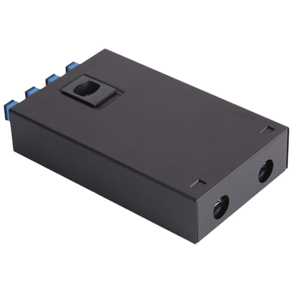
Secure cables in trays or conduit and fasten with hook-and-loop ties to prevent compression. For ducted runs, clear the conduit and use a silicone-based lubricant compatible with the cable jacket. A fiber wall socket (also called an optical termination outlet or FTTH outlet) is the critical endpoint where your home's fiber optic cable connects to the Optical Network Terminal (ONT). It ensures a clean, stable interface between the ISP's fiber network and your router—impacting speed, latency. Running fiber internally involves extending this high-speed link from the service entry point to a centralized location, such as a dedicated media closet or network rack. The processes. Once your plan is in place, the next step is to lay your cable. I have fiber optic cable (white plastic, about 1mm in diameter) running into my unit, installed by the provider. I decided to move the ONT, which is working fine, but I am not sure of the best way to stick the cable to the wall.
[PDF Version]
A well-built fiber link rarely fails, but when it does the symptoms can be short, confusing, and expensive to chase. This guide lists the actual, field-proven problems technicians encounter most often and gives step-by-step troubleshooting actions you can copy into your. Fiber-optic cables are the backbone of modern connectivity—powering 5G networks, global internet backbones, and data center interconnections with near-light-speed data transmission. While these cables are engineered for durability (with some rated to last 25+ years), they are not invulnerable. However, in real-world installations, whether underground, aerial, or in harsh industrial environments, fiber cables can and do fail. This guide will walk you through diagnosing and resolving common. Workplaces rely on fiber connections to move data without delay. Issues like signal loss, physical damage, and poor connections can degrade performance or cause complete outages. Knowing how to recognize and diagnose these problems quickly ensures.
[PDF Version]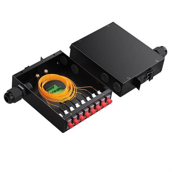
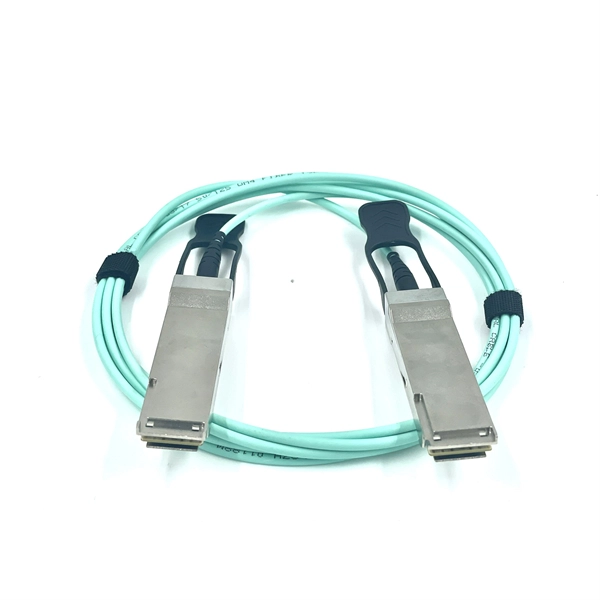
Single-mode fiber (SMF) supports distances up to 40-100+ kilometers for standard applications, while multimode fiber (MMF) is typically limited to 300 meters to 2 kilometers. The actual distance depends on factors including fiber type, wavelength, network equipment, and signal. Network SwitchNetworking DevicesOptics and TransceiversFiber Optic CablesCopper CablesPatch Panels, Cassettes, EnclosuresTesters and ToolsOptical Networking DevicesPower Newsroom Home HPC Data Center Enterprise Network Cabling WDM, OTN, PON Software Hardware Newsroom Home/ Cabling/ Fiber Optic. First is the attenuation of the optical fiber. Attenuation is the weakening of light as it comes in from the transmitting end of the fiber and out of the transmitting end. Many factors cause. Uses a small core (8-10µm) to allow only one light mode, reducing signal attenuation and dispersion.
For such cables, we recommend using at least a 1. It's important to consider not only the rigidity of the jacket but also the breakout point of the assembly, where the strands exit the jacket and are encased in. 8 core single mode fiber optic cable should be selected by fiber mode, core count, cable structure, jacket material, installation route, tensile strength, attenuation test, reel length, and quantity. Selecting the right conduit ensures the cable's longevity, prevents signal degradation, and supports efficient installation and maintenance. They feature low attenuation benchmarks 2 and minimal dispersion. They use OS1 or OS2 OS1 or OS2 classifications to. Understanding the physics behind Single Mode vs Multi‑Mode Fiber is essential for selecting the right conduit for any optical network. Single‑mode fiber (SMF) employs an ultra‑narrow core—typically 8 to 10 µm in diameter—that permits only one propagation mode.
[PDF Version]Contact us for competitive quotes on any of our power communication and smart grid products
Get a Quote