
Products such as low-voltage switchgear and controlgear are subject to CCC certification (China Compulsory Certification) as they are safety-related components in electrical systems. Affected products generally require CCC certification in order to be approved for import and distribution in China. Among the recently announced or newly effective standards is (1) GB/T 14048. It specifies the following issues on China Compulsory Certification (CCC) of low-voltage components: scope of application, base standards, certification. On 13 November 2023, the Chinese Certification and Accreditation Administration issued an Announcement to change the compulsory standard for switches and control equipment.
The IEC 61439-1 sets the thermal limit in busbars working at the maximum working load. Here, 140°C (which is 105K over the ambient temperature of 35°C) is the upper safe temperature limit. Continuous, real-time busbar temperature monitoring and hot spot detection for MV & HV switchgear, substations and power plants — EMI-immune, calibration-free, fully SCADA-integrated. Thermal monitoring locations include: Eaton Exertherm CTM solution for MV switchgear. Standards mandate that busbars, when carrying their rated continuous current for extended periods, must not experience excessive temperature rise.
Guidance on settings for the 132kV system is given in CP338, and for the 33kV and 11/6. Relay protection is essential to ensure the stability, reliability, and safety of electrical power systems. Protective relaying is the backbone of fault detection and system isolation in As transmission systems grow increasingly complex with integration of. This document states the Electricity North West Limited policy for protection for all high voltage systems. It covers standard codes, wiring practices, and norms for protecting generators, transformers, and lines, and provides detailed. Abstract: Covered in this recommended practice is the protection of bus and switchgear used in industrial and commercial power systems. Protection selectivity is partly considered in this report and could be also re-evaluated.
Front- and rear-access switchboards align at the front and the rear. Bus maintenance and cable entry and exit require rear access. Their placement directly affects current capacity, heat dissipation, copper consumption, cabinet size, and even installation safety. If the main section is deeper than others, due to physical size of the main device, the necessary offset in lineup will occur in front, and the main section will be. A large single panel, frame, or assembly of panels on which are mounted on the face, back, or both, switches, overcurrent and other protective devices, buses, and usually instruments. In most assemblies you will find horizontal main bars, vertical risers, neutral and equipment-ground buses, and purpose-designed. Article 408 covers the specific requirements for switchboards and panelboards that control power and lighting circuits.
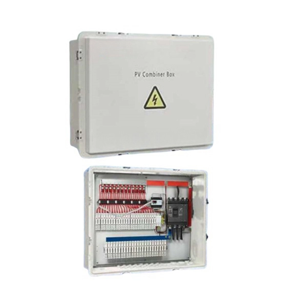
When drawing up a single line-diagram, a great number of possible combinations of incoming and outgoing connections have to be considered. The most common ones are shown in the following di.
Busbar problems are often incorrectly identified as harmonic currents caused by non-linear loads. According to MET Group's field data, the primary causes of busbar and tap-off switch failures include aging, loosening connections over time, and poorly installed new systems. Fault arcs on busbar sets and switchboards Title Author Subject Fault arcs on busbar sets and switchboards-The probability of appearance of a fault arc on a set of busbars cannot be considered as non-existant. How to reduce arcing probability, limiting consequences. This generates both thermal stress (I²t heating) and mechanical stress (electrodynamic forces between conductors). Bus bar supports spacing, and bracing must be designed to withstand. switchgear busbar sizing decisions should start from voltage class, fault level, and installation environment. Clear interface data reduces site rework between transformer, switchgear, breaker, RMU, and. Additionally, busbar faults can create arc flashes, posing a major safety hazard.
[PDF Version]Contact us for competitive quotes on any of our power communication and smart grid products
Get a Quote