
Typically composed of a durable metal frame or bracket, Secondary Racks are designed to be securely mounted onto utility poles or structures. They feature multiple attachment points or slots that allow for the tidy and efficient routing of secondary conductors along the pole or. Primary distribution systems consist of feeders that deliver power from distribution substations to distribution transformers. A feeder usually begins with a feeder breaker at the distribution substation. Many feeders leave substation in a concrete ducts and are routed to a nearby pole. The SDB can be fitted with terminal blocks for custom. ACS takes the basic idea of zone wiring and combines it with pre-cut, pre-tested cable and plug-in connectors, to provide power and telecommunication systems that can be installed under raised floors (The Intelligent Floor), or in accessible ceilings (The Intelligent Ceiling).
[PDF Version]
An efficient photovoltaic (PV) tracking system enables solar cells to produce more energy. However, commonly-used PV tracking systems experience the following limitations: (ⅰ) they are mainly applied.
Always use 2 splice plates per length of tray and SBH and CNH splice nuts and bolts to fasten them in place. EzyStrut splice bolts have a smooth head which should be installed on the inside of the tray's side wall. When a wire cable tray is cut, the fact that a. The ET 'EzyTray', ET3 and ET5 are designed to work how you want to work around your project. Unlike the CT range of tray, the ET range does not come with pre-made fittings, rather, it uses accessories that allow you to bend, rise, or join straight lengths together either in series or to fabricate a. The adjustable corner piece SRS is pushed inside the cable tray and attached with the included screw set. The range for adjustable corner piece SRS is 0-75°. The range for adjustable. Calculate horizontal, vertical, or compound cable tray offsets based on bend angle, offset distance, and available installation space. This involves a few essential steps to ensure a successful bending process.
[PDF Version]
Among the most common options are fixed and adjustable cable tray support brackets. The right choice can significantly impact the efficiency and safety of your installation, so it's crucial to understand the differences between these two types. When it comes to organizing electrical cables and conduits, choosing the right support brackets is essential. es in the industrial environment. Our cable support. LB3 brackets can be used for mounting lighting units at adjustable angles and are fixed to both the sidewall and the base of the cable tray. The mechanical and electrical characteristics, tests, certifications, overall quality management, recommendations mentioned in this technical guide only apply to our own cable management ranges and cannot under any circumstances be transposed to si osure, overheating or. en completely installed, without damage either to conductors or structural system use maintain spacing or to keep cables in place when the tray is ect the minimum bend ra-dius for cables as they exit the bottom of the cable tray.
[PDF Version]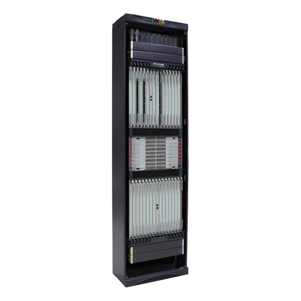
Light entering the core of the optical fiber at an angle greater than the acceptance angle may not propagate the length of the fiber. For light to propagate the length of the optical fiber, it must enter the core at an angle that does not exceed the acceptance. The performance of a fiber optic splice is determined by a number of factors, including the quality of the fiber, the cleanliness of the splice, and the techniques used to make the splice. Intrinsic factors, such as the refractive index of the fiber, are those that are inherent to the fiber itself. High splice loss occurs when the fusion between two fibres does not achieve proper core alignment, resulting in excessive optical signal attenuation. The root causes typically include: To resolve this, first check the fibre ends. Ensure they are clean using alcohol wipes or specialized fibre. Concerning angle-cleaved fiber ends, it is often of interest how large the cleave angle needs to be to avoid significant reflection into the core mode.
[PDF Version]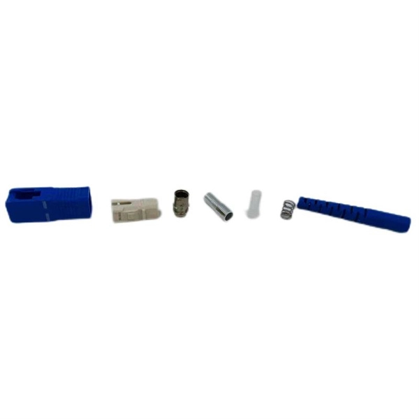
The fiber optic 90-degree bend refers to the minimum radius required when cables must change direction at right angles. Similar to how a garden hose restricts water flow when kinked, fiber optic cables experience performance degradation or complete signal loss when bent too sharply. Exceed it once and you might get away with it.
Contact us for competitive quotes on any of our power communication and smart grid products
Get a Quote