
This document discusses various optical modulation and demodulation schemes. It describes modulation techniques such as amplitude shift keying, frequency shift keying, and phase shift keying that encode information by varying the amplitude, frequency, or phase of an optical. The invention of the laser by Schawlow, Townes and Maiman [1,2] ushered in the era of deep-space optical communications. Here was a source of intense, highly directed optical energy that could produce coherent radiation, like radio frequency (RF) transmitters, but at much higher optical. Optical modulation allows one to control an optical wave or to encode information on a carrier optical wave. Optical modulation enables many key functions in. Abstract: Performance and implementation complexity of various binary and nonbinary modulation methods with coherent, differentially coherent and noncoherent detection are compared. A modulation scheme continuously alters the property or properties of a waveform.
[PDF Version]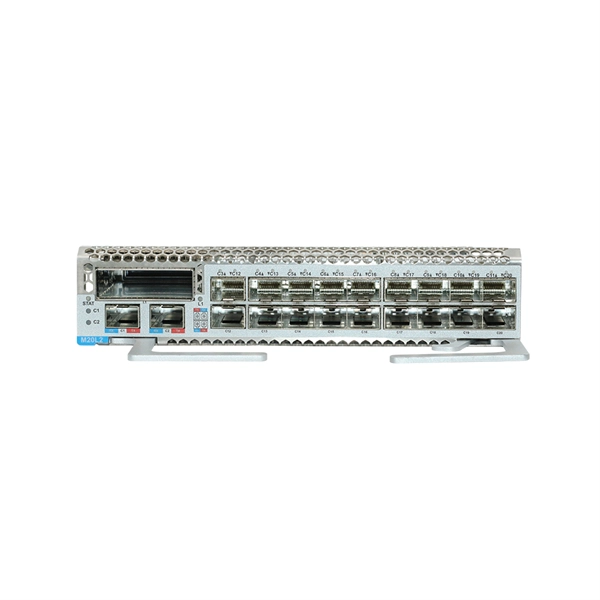
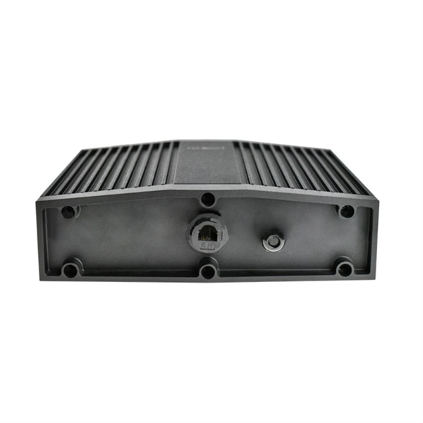
The optical module, known as Optical Transceiver in English, is a general term for various module categories, including optical receiver modules, optical transmitter modules, optical transceiver modules, and optical forwarding modules. Optical modules typically have an electrical interface on the side that connects to the inside of the system and an optical interface on the side that connects to the outside. The optical module serves as a crucial component in optical fiber communication systems, operating at the physical layer, which is the lowest layer in the OSI model. Its primary function is to achieve optoelectronic conversion by converting electrical signals into optical signals and vice versa. An optical module works at the physical layer of the OSI model and is one of the core components in the fiber communication. Optical Modules (also known as Optical Transceivers) are critical components in fiber optic communication systems. As the demand for faster and more reliable internet and data services grows, understanding these devices becomes increasingly important.
[PDF Version]
The Pyongyang Semiconductor Factory was completed in April 1987 as a prototype production plant with assistance from the United Nations Development Program. It claims sovereignty over South Korea. Juche, an ideology of national self-reliance, was introduced into the. In 1960, North Korea made a relatively easily obtainable Ge single crystal among silicon and germanium (Ge), which are most commonly used in semiconductor material development, and made a rudimentary type of semiconductor device, that is, a point contact diode. Research facilities that develop and produce semiconductors in North Korea include the Kim Il-sung University's Department of Electronic. Contrary to popular belief, North Korea is not just a subsistence economy; it also produces goods stamped “made in North Korea”. Admittedly, these are modest compared to giants such as China and India. In. North Korean leader Kim Jong Un inspects a new weapons factory in an undisclosed location, North Korea, Aug.
[PDF Version]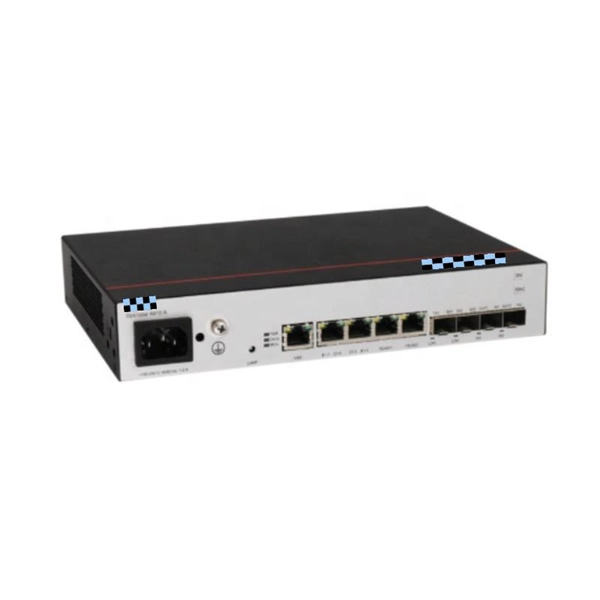
An optical module is a typically hot-pluggable optical transceiver used in high-bandwidth data communications applications. Optical modules typically have an electrical interface on the side that connects to the inside of the system and an optical interface on the side that connects to the outside world through a fiber optic cable. The form factor and electrical interface are often specified by an interested group using a (MSA). Optical modules can either plug into a front pa.
In order to save power within the module, optical modules have been made that used the digital interface definition, such as the CEI, but without retiming the signals within the module.OverviewAn optical module is a typically hot-pluggable optical transceiver used in high-bandwidth data communications applications. Optical modules typically have an electrical interface on the side that connects t. There have been multiple variants of the electrical interface of optical modules that have been used over the years. The earliest forms of optical modules had an analog electrical interface. In the transmit dir.
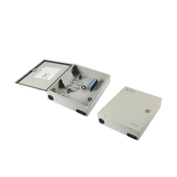
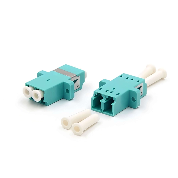
There are multiple methods to use for attaching fiber optic modules to an electro-optics assembly, and may include: soldering, conductive adhesives, or mechanical assembly. The Printed Circuit Board (PCB) at the heart of these modules is no longer a simple substrate but a highly engineered system. Designing and producing these complex PCBs presents formidable challenges, requiring a convergence of disciplines—from high-frequency signal integrity and advanced thermal. Extend Routed Optical Networking use cases to regional and ultra-long-haul DWDM applications. Transmit 400G wavelengths up to 120 km with coherent ZR and enable long-haul transmission with OpenZR+. They protect and organize the sensitive connection points between optical fibres and play a decisive role in the quality, reliability and ease of maintenance of the entire network., two fiber connectors) such that light can reliably pass from one to the other with minimal insertion loss and maximum return loss. By following these detailed steps, the installation of your Fiber Splice Closure will be secure, organized, and maintained, ensuring high performance and longevity of your fiber optic network.
[PDF Version]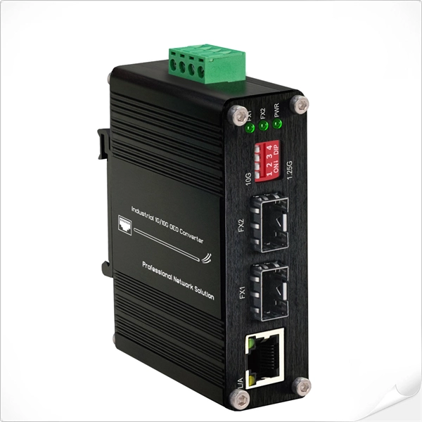
Standard 10GbE SFP+ and 25GbE SFP28 optics can be readily inserted, recognized, and utilized in the 100GbE QSFP28 receptacle using a (QSA28) pluggable adapter. Explore Cisco products and features to empower your purchase with data sheets, white papers, end-of-life notices, and more. Access training tailored to your needs. Work toward a specific role or certification, deploy or. Deployment flexibility with 800G (dual 400G), 400G, 100G, 50G, 40G, 25G, 10G or 1G modules. QSFP+ Universal transceiver for 40G operations over duplex multi-mode and single-mode fiber. Interoperable with IEEE 40GbE LR4 and LRL4 for easier migrations from 10G to 40G and to single mode fiber 100G. FS 10GbE SFP+ module solutions provide a wide variety of 10 Gigabit Ethernet connectivity options for data centers, enterprise wiring closets, Internet Service Providers (ISPs) applications. The wavelength can be 850 nm, 1310 nm, or 1550 nm, and the transmission distance ranges from 0. The 10GbE SFP+ receptacle will also recognize 1GbE SFP transceivers.
[PDF Version]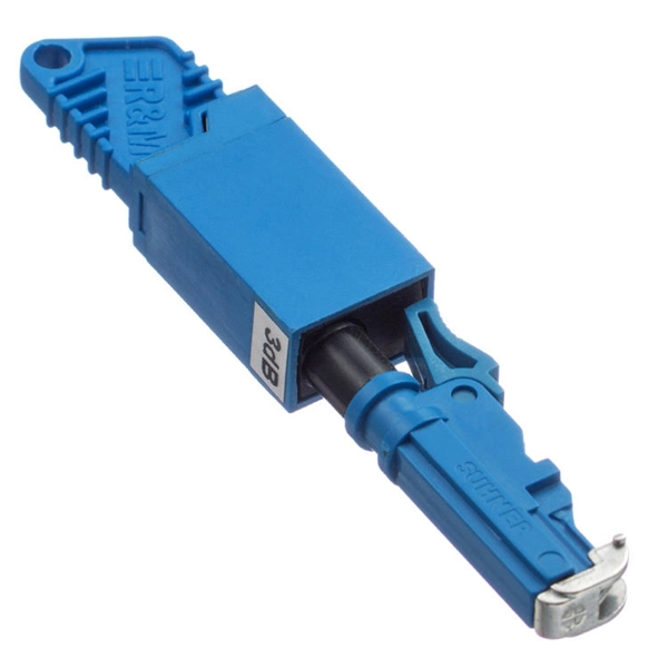
Electrostatic discharge can damage the internal laser driver and digital signal processors. Follow these ESD protection practices: Always wear an ESD wrist strap grounded to an antistatic mat. Use ESD-safe containers for storage and. Common Problems Encountered in Optical Module Applications In real-world deployments, It failures generally fall into several key categories. Most issues are not isolated but result from compatibility, environment, or improper operation. The exact cost of ESD induced failures to the Electronics Industry is difficult to calculate since many of. The number of failures caused by electrostatic discharges (ESD) has been increasing for some time now. The paper will give an overview about possible causes for ESD. This guide from ESOPTIC provides practical tips on optical transceiver insertion, removal, cleaning, and ESD protection, ensuring that your modules operate efficiently and safely. Before installing an optical transceiver, always make sure the device is powered down (unless hot-swapping is. 2022-07-01Assigned to JPMORGAN CHASE BANK, N., AS COLLATERAL AGENTSECURITY INTEREST (SEE DOCUMENT FOR DETAILS)., II-VI INCORPORATED, II-VI PHOTONICS (US), INC.
[PDF Version]
A myriad of compatible fiber optic transceivers is used in network deployments. However, there are still concerns about quality, interoperability, and compatibility issues when selecting optical modules.
Contact us for competitive quotes on any of our power communication and smart grid products
Get a Quote