
To perform an OTDR test correctly, you must: 1. Set core parameters (Wavelength, Distance, Pulse Width); 4. Run the test (Real-time or Average); 5. An Optical Time Domain Reflectometer (OTDR) is the most powerful tool for characterizing fiber optic networks. It works like "radar for fiber optics," sending light pulses down the fiber and analyzing the reflected light to measure loss, locate faults, and verify installations. Automated: In addition to GIS mapping and powerful analytics, the cloud-native EXFO RFTM offers automated test configuration, execution and results, as well as open APIs. Smart: iOLM. FOA "Quickstart Guides" are short, simple guides to basic fiber optic tests. Learn step-by-step how to use FiberComplete PRO on your VIAVI OTDR for maximum. The AQ7277B delivers precise, high-resolution reflection analysis for fiber-optic network monitoring and troubleshooting.
[PDF Version]
To perform an OTDR test correctly, you must: 1. Set core parameters (Wavelength, Distance, Pulse Width); 4. Run the test (Real-time or Average); 5. OTDR (Optical Time Domain Reflectometer) is a commonly used test equipment in fiber optic communications, which can help detect the loss, fault points and other performance indicators of fiber optic lines. For fiber optic engineers and technicians, mastering the use of OTDR Tester is the key to. In this video, we provide a step-by-step guide on how to operate an OTDR (Optical Time-Domain Reflectometer) for accurate fiber optic testing. more In this. OTDR settings are a balance between dynamic range, acquisition time, spatial resolution and accuracy.
OTDRs display trace results by plotting reflected and backscattered light versus distance along the fiber, characterizing any reflective and non-reflective events in a fiber link. These reflections, known as Fresnel reflections, are meticulously measured by the OTDR to pinpoint the location of these events within the fiber link. Due to the inherent structure of the fiber and microscopic imperfections within the glass, a small portion of the light pulse scatters in various. An optical time-domain reflectometer (OTDR) is an optoelectronic instrument used to characterize an optical fiber. The OTDR is also commonly used to create a "picture" of fiber optic cable when it is newly installed. However, its value lies not only in taking measurements but also in correctly interpreting the records (traces) it generates.
To perform an OTDR test correctly, you must: 1. Set core parameters (Wavelength, Distance, Pulse Width); 4. Run the test (Real-time or Average); 5. FOA "Quickstart Guides" are short, simple guides to basic fiber optic tests. All are written in the same straightforward format: what equipment do you need, what are the procedures for testing, options in implementing the test, measurement errors and documenting the results. It works like "radar for fiber optics," sending light pulses down the fiber and analyzing the reflected light to measure loss, locate faults, and verify installations. This guide dives deep into OTDR technology, its applications, and how it integrates with modern components like optical transceivers.
Use launch cable to measure the first connector of the link. Increase pulse width for more dynamic range. OTDR settings are a balance between dynamic range, acquisition time, spatial resolution and accuracy. To minimize testing time, compromises must be made on accuracy (detecting low loss. OTDR (Optical Time Domain Reflectometer) testing is a vital technique for characterizing and troubleshooting optical fiber networks. It provides valuable information about fiber length, loss, and the location of events like splices and connectors. However, like any measurement technique, OTDR. An OTDR works by transmitting high-power light pulses into the fiber and measuring the light reflected from any event or the end of the fiber due to a change in the refractive index. But you may wonder, "How can I use an OTDR to locate splice loss and connector issues?" The answer is simple, with the right OTDR, you can pinpoint problem areas along the fibre.
[PDF Version]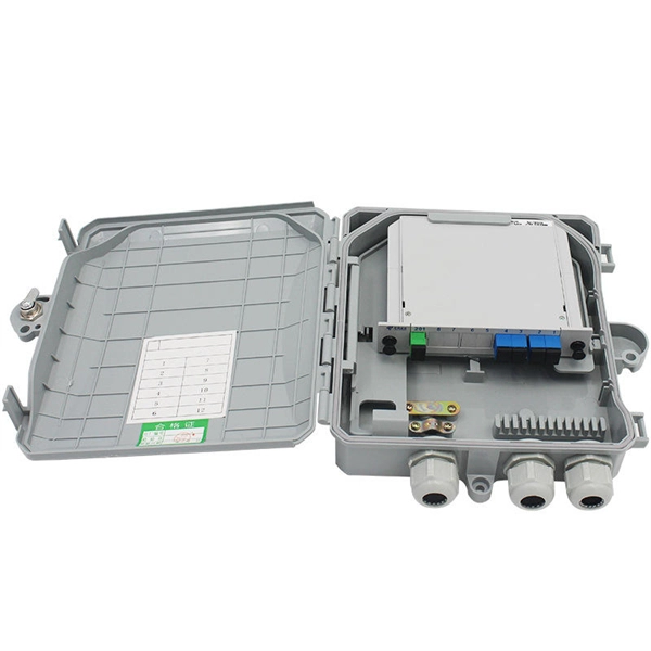
FOA procedures, such as OFSTP-7 (single-mode) and OFSTP-14 (multimode), align with TIA and IEC standards. Fiber Optic Testing Testing is used to evaluate the performance of fiber optic components, cable plants and systems. As the components like fiber, connectors, splices, LED or laser sources, detectors and receivers are being developed, testing confirms their performance specifications and helps. ondition of the cabling system and its components with an op cal time domain reflectometer (OTDR). The condition of the fibre end fac g with an OLTS and an OTDR and have obtained a certificate as proof thereof shall execute the tests. 11 Optical Fiber Systems Subcommittee and published in September, 2022. They describe how to set a '0 dB' reference, control mode power distribution, and use proper wavelengths.
Once installed, the splitter simply becomes one source of loss in the cable plant and is tested as part of that cable plant loss for insertion loss testing. First we should define what these. Here Kingfisher's experienced engineers share their experience in best practices and procedures for fiber optic testing related mostly to installation and maintenance. We hope that by sharing our knowledge, we will help grow our industry. Please enjoy & pass on these notes. Other Passive Devices There are other passive devices that require testing. Insertion loss testing of the optical splitter is very important to ensure compliance to the optical parameters of the manufactured splitter in accordance with the GR-1209 CORE specification. Signal loss within a system is expressed using the decibel. In fiber optic networks, particularly in FTTx (Fiber to the x) and PON (Passive Optical Networks) deployments, splitters play a central role in distributing the optical signal from a single source to multiple destinations.
[PDF Version]
Test the Repair: Before re-installing the harness, test the repaired section with a multimeter for continuity and correct resistance. A faulty pigtail can lead to anything from intermittent malfunctions to complete system failure, even posing a significant safety hazard. It provides a plug-and-play repair solution that restores OEM fit, seal, and electrical reliability. Pigtails are. A single defect in a flange—whether a microscopic crack in the forging, a deviation in bolt hole alignment, or an improper surface finish—can lead to gasket blowout, fugitive emissions, or structural failure under high pressure. For EPC contractors, QA/QC engineers, and procurement managers. from spring clip the spring the fixed clip clip to compress, side). This allows fixed releases clip then wing peater so from •should Always remember be required. Common problems include rusted connectors, damaged. Is the failure symptom that no data traffic can get from one side of the repeater to the other, or that a hard error such as a beaconing condition is present on the ring? Go to page 9. For some of the troubleshooting steps mentioned on.
[PDF Version]
Comprehensive guide for SCADA fibre optic cable selection in substations & BESS. Hi, my name's Pete Suttmeier with Lightera Specialty Solutions division in Avon, Connecticut. Abstract: The design, installation, and protection of wire and cable systems in substations are covered in this guide, with the objective of minimizing cable failures and their consequences. Printed in the United States of America.
An optical waveguide is a physical structure that guides in the. Common types of optical include waveguides, transparent made of plastic and glass, liquid light guides, and liquid waveguides. Optical waveguides are used as components in or as the transmission medium in local and long-haul systems. They can also be used in.
Contact us for competitive quotes on any of our power communication and smart grid products
Get a Quote