
This document provides guidelines for installing high voltage power cables. It discusses planning the cable route and laying procedures. Key considerations
It applies to cable trays made of steel, stainless steel, aluminum, or other metallic materials. The standard ensures these systems can handle the
Cable tray is alternatives to wire ways and electrical conduits, which completely enclose cables. Study types of cable trays, purpose, advantages.
This guide covers cable ladder systems, cable tray systems, channel support systems and associated supports intended for the support and accommodation of cables and possibly other electrical
All fittings are available in sizes and types corresponding to the straight cable tray sections. Elbows - Horizontal and vertical elbows enable directional and elevational changes,
Cable tray installed in a hazardous location must contain only those cables that are appropriate for this type of environment as defined in Chapter 5 of the NEC.

Browse our expert technical content on HV cable current rating calculations, electrical cable systems design and testing methods & more articles.
The cable ampacity installed in solid tray will be similar to cable installed without spacing in accordance with CEC Rule 12-1210 (3). Solid tray will carry the same type of conductors as ventilated trays.
15° and 22.5°: Ideal for thick, heavy, or high-voltage cables with large bending radii. They require the most horizontal space but offer the smoothest transition and the easiest cable pulling experience.
A cable tray system is an assembly of metallic cable tray sections and accessories, that forms a rigid structural system to support cables.
A cable support system consists of cable support lengths and system components, such as cable support fittings, support elements, mounting elements and system acces-sories. The cable support
The phase sequence and the types of arrangement for the cables are also stated in the Electrical High Current Facilities Regulation, the international standards and
This is a common problem with regard to the assembly of power cables in cable trays, an example of which is shown in Figure 5.
High-quality Hot-Dip Galvanized (HDG) Cable Trays, including Perforated Tray, Cable Ladder, Horizontal Bend, Vertical Bend, Tees, Reduce, End Cap, and
Cable ladder and cable tray systems The following recommendations are intended to be a practical guide to ensure the safe and proper installation of

How to make a 0-90° vertical angle for cable trays? Elbow joint RVS is pushed inside the cable tray and attached with the included screw set. Elbow joint RVS
Cable trays are a common method for organizing and supporting cables in various settings, but what about high voltage cables? Can they be safely installed in cable trays? In this
Allows to rotate the cable trays in a horizontal section, so we can place horizontal cable trays with the bottom facing a wall. Placing channel cable trays upside
For safety-critical systems, here is some advice from a DOE handbook: Cable Tray Separation: In general, physical separation of cable trays for redundant safety-class circuits should
In our energy business, we design, produce, distribute and install cables and systems for the transmission and distribution of power at low, medium and high voltage. In telecoms, the Group is a
Layered Separation: Strong current and high-voltage cables are positioned apart from low-current, low-voltage instrumentation cables. Layered separation
Deflection is the vertical sag of the tray at its mid point and is at right angles to the tray''s longitudinal axis. The issue of deflection is not one of a structural nature, but a cosmetic (appearance) one.
Rollers are used to support and guide LV, MV & HV cables into open trenches without damaging cable sheaths and incurring overbending stresses on power
The flexible horizontal adjustable splice plates are designed to allow for horizontal direction changes when standard horizontal fittings do not conform. The splices are furnished in pairs and include
Complete cable tray manual for electrical engineers and designers (on photo: power cable management ladder tray systems assembled aluminum
Cable Tray Fittings: Fittings are required for change in size or direction of the cable tray. Designs of fittings are done keeping in mind the radius of the bend. At KMC,
A practical guide to product selection and installation This guide for engineers and installers has been developed by ABB as a practical reference regarding cable tray characteristics, installation, and
NEMA VE 1-2017 Specifies requirements for metal cable trays and associated fittings designed for use in accordance with the rules of Canadian Electrical Code, Part I and the National Electrical Code®
Calculate horizontal, vertical, or compound cable tray offsets based on bend angle, offset distance, and available installation space. Use this tool to estimate sloped section length, horizontal run
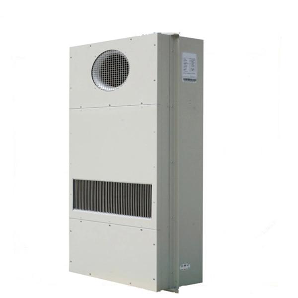
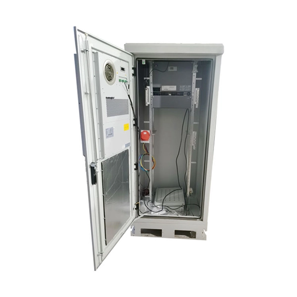
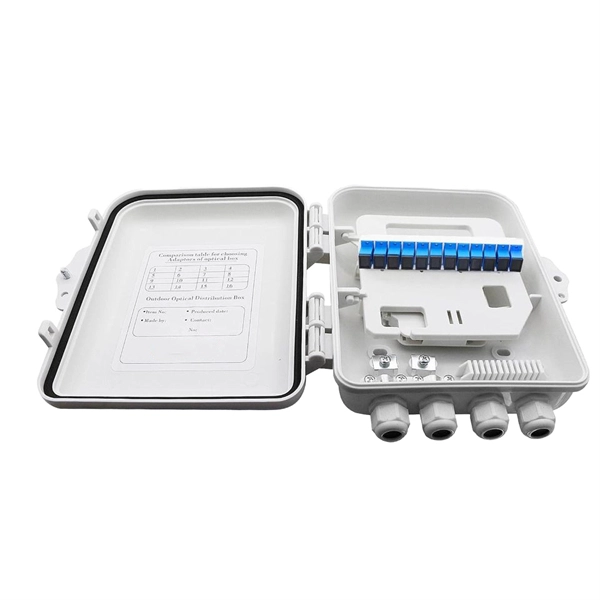
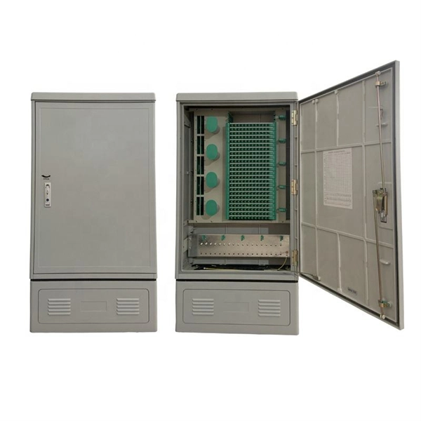
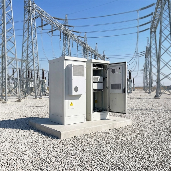
Contact us for competitive quotes on any of our power communication and smart grid products
Get a Quote