
The single-line diagram is the blueprint for electrical system analysis. It is the first step in preparing a critical response plan, allowing you to become thoroughly familiar with the electrical distribution
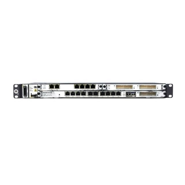
Incoming and outgoing feeders in switchgear are equipped with circuit breakers and disconnection and earthing switches. Current and voltage
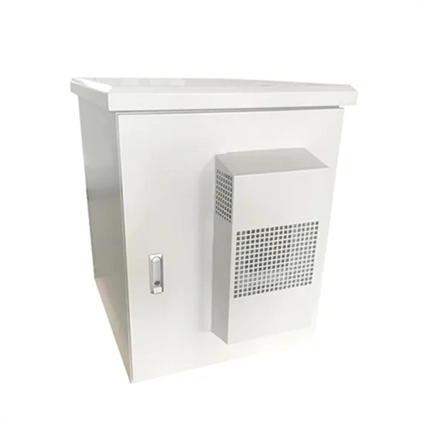
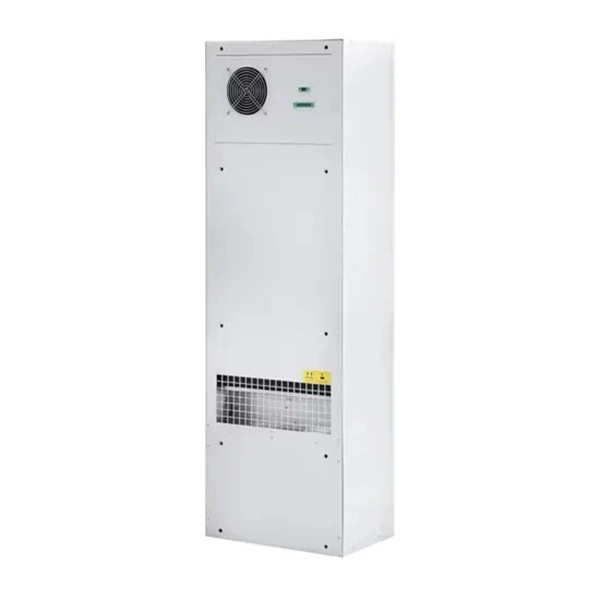
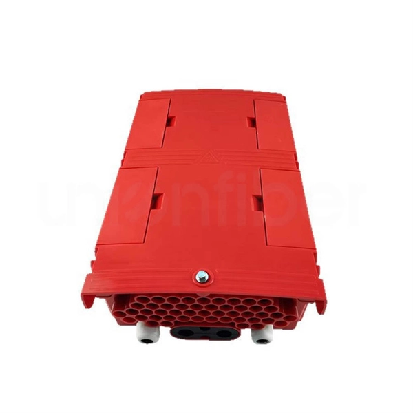
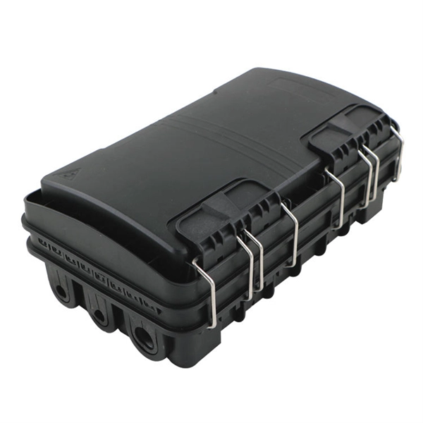
Weatherproof Distribution Boxes These serve specific outdoor purposes, with rain, dust, and extreme temperatures sealed shut, protecting any
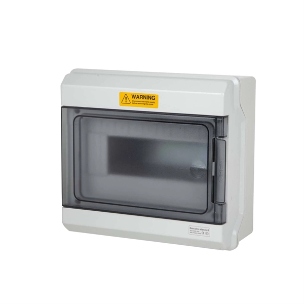
Then, what matters should be paid attention to in and out of the meter box (small power distribution board)? Here is a brief introduction. 1、 Rain proof measures
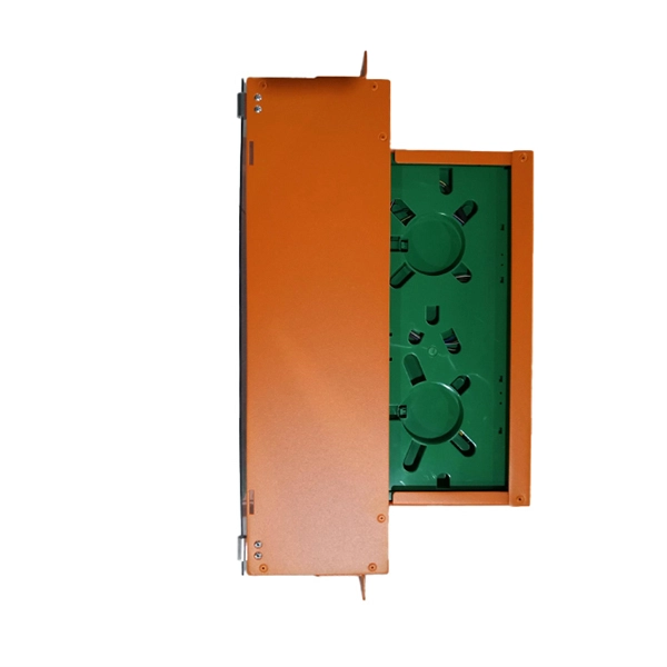
These fire-resistant connection boxes and small distribution boards exclusively serve towards ensuring the maintenance of performance by installations over a certain period of time in the event of a fire.
Figure 4 – Single-line diagram of modernized load-centre power distribution system where 480V load-centre unit substation and 2400V master
Both incoming and outgoing lines are connected through circuit breakers having isolators on their either end. Whenever repair is to be carried over the line

Distribution board fault current rating The manufacturer is responsible for ensuring the capability of the equipment between the incoming and the outgoing terminals of the distribution board, which includes
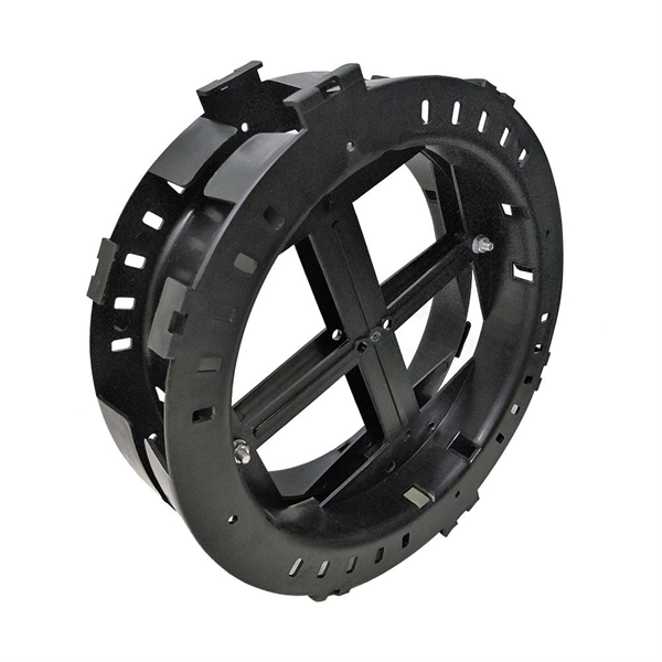
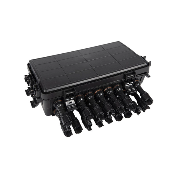
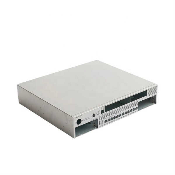
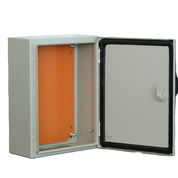
A distribution box, also known as a power distribution box or electrical distribution box, is used to distribute electrical power safely to multiple
Explore detailed configurations of high voltage incoming and outgoing feeders in switch yards—visualize routing, protection setups, and connection layouts to
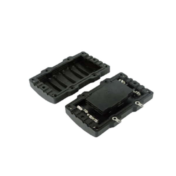
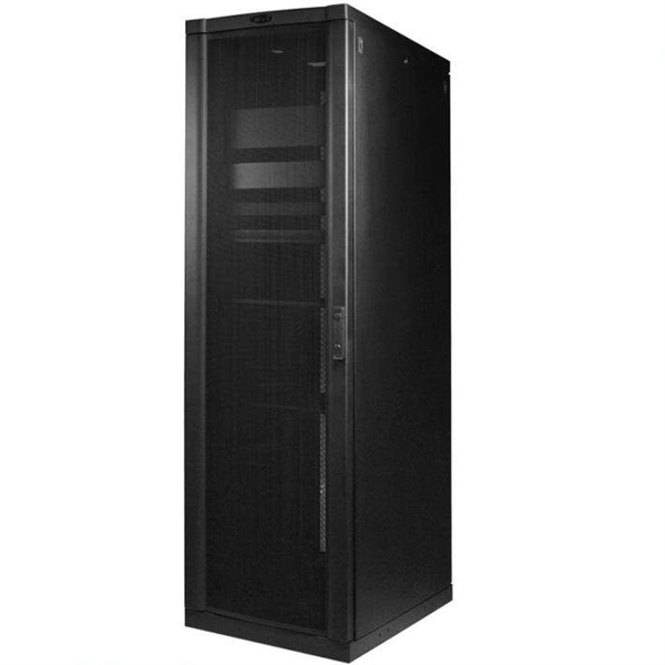
A distribution structure divides and sends power to branch circuit protection devices and then to branch circuits to power downstream loads. Power moves from the incoming structure to the distribution

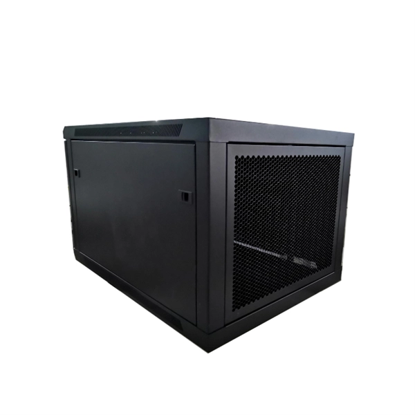
Interior: Prepared for installation of distribution panels and CombiLine-M modular distribution panels Cable entry: Top, bottom or both Ventilation system: Ventilation takes place via channels in the rear
General Technical Particulars for LT Distribution Boxes : - The L.T. Distribution Boxes should be of the dimensions as per the drawing & details in the table furnished.
Continuous operation during fire conditions. The fireproof wiring box is designed for connecting and/or branching cables of installations which guarantee continuous operation during fire conditions. | 2.

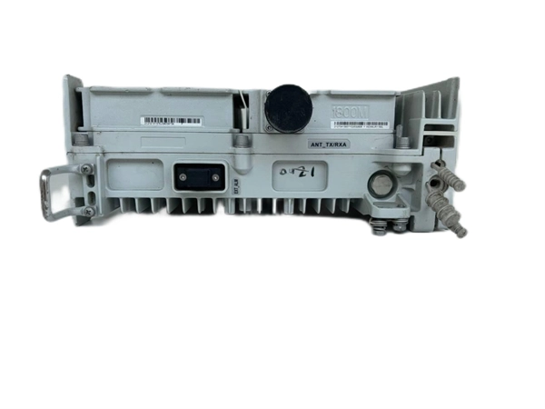
1 - Power Distribution Panel: Power distribution panel is used for utilization of equipment. Power supply is received from LT panel and distributed to the
Zone segregation of cables, buried conduits, fire retardant coating, fire walls and physical separation are all acceptable methods of providing protection for cables.
In the design of the incoming and outgoing lines of the distribution box, the length of the wires entering the box is two-thirds of the perimeter of the
The design of the distribution box needs to be firmly installed with the switch box, mainly to facilitate the later maintenance work; the location of the fire
Substation Single Line Diagrams66/11 Kv Outdoor Substation11 kV/400 V Indoor SubstationThis technical article describes single line diagrams of two typical power substations 66/11 kV and 11/0.4 kV and their power flow, principles of incoming lines (incomers) and outgoing lines (feeders), busbar arrangement functionality and so on. Regarding elements in single-line diagrams, they were already explained in previous article, so if you d...See more on electrical-engineering-portal ABB Group
ABB offers an innovative enclosure system for fire prevention, which is constructed of fireproof materials, features optimum technology and is available in a variety of economical designs.
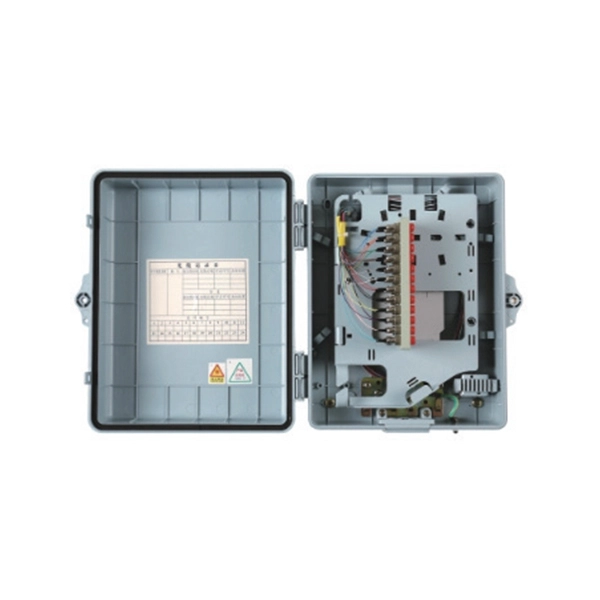
Trace the outgoing line circuit: Analyze the outgoing line circuits of the distribution box one by one, understand the load equipment and protection
Incoming and outgoing feeders in switchgear are equipped with circuit-breakers and disconnection and earthing switches. Current and voltage
1. Scope: This specification covers technical requirements of design, manufacture, testing at manufacturer''s works, packing, forwarding, supply and unloading at store/site and performance of
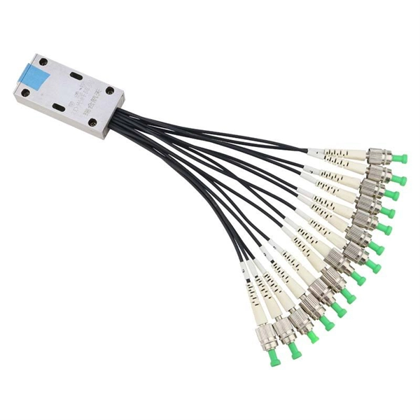
ass shall be provided at the bottom of the Box One for incoming cable and one outgoing cable. Detachable plat s shall be provided for fixing of cable glan 1.6 The Drawings shown below are
Contact us for competitive quotes on any of our power communication and smart grid products
Get a Quote