
A fiber optics network diagram illustrates how high-speed data travels from an internet service provider to end users. These diagrams help engineers plan
There is really no way to generalize on the design process for fiber to the home (FTTH) networks - or any fiber optic network for that matter - since every system
Download scientific diagram | Fiber optic network example with ring topology providing STM-4 backbone from publication: Application of fiber-optic techniques in the transport and access
The Management Station requires fault mask, agent configuration, agent event configuration and agent traps configuration settings to supervise the fiber optic switch using Simple Network Management
Idea of a network diagram Fiber optic network diagrams represent the architecture and connectivity of fiber optic systems, and their design
This template showcases a professional layout for Fiber-to-the-Home and Fiber-to-the-Building setups. It visualizes the connection between a central office and
We propose to close the communications signal path, resulting in a ring topology where a resonance condition could be implemented. A PLC
This paper proposes a reliable hybrid 4 × 10 Gbps fiber optic-FSO based ring architecture. The proposed architecture aims to provide reliable and band
Learn why utility-scale solar facilities are most commonly networked using fiber optic technology and how to best maintain it.
Download scientific diagram | Schematic of FOC cable connection for multiple network applications from publication: Performance Analysis and Monitoring of
Fibre loops, also known as fibre rings, refer to a network setup where each node or building connects to the next in a loop formation using fibre optic cables. This
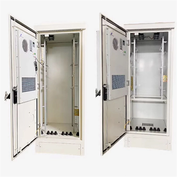
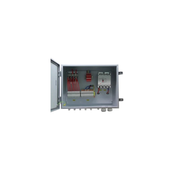
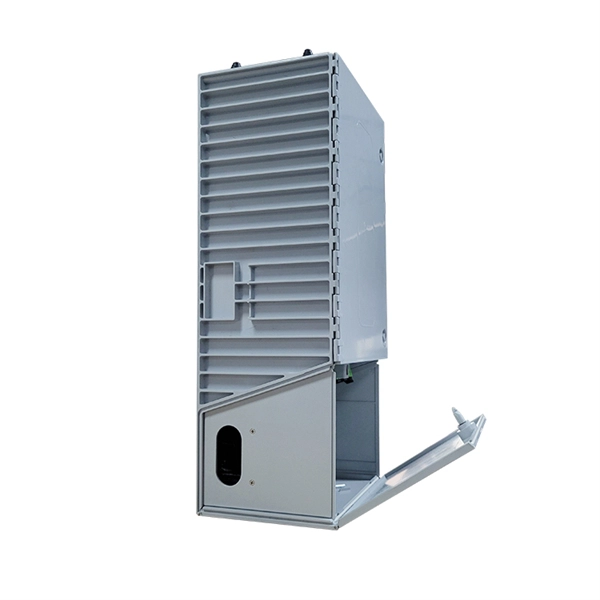
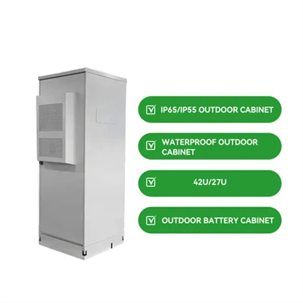
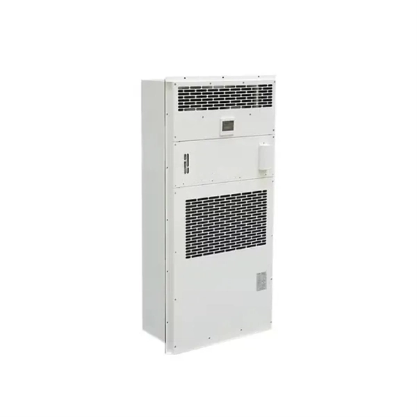
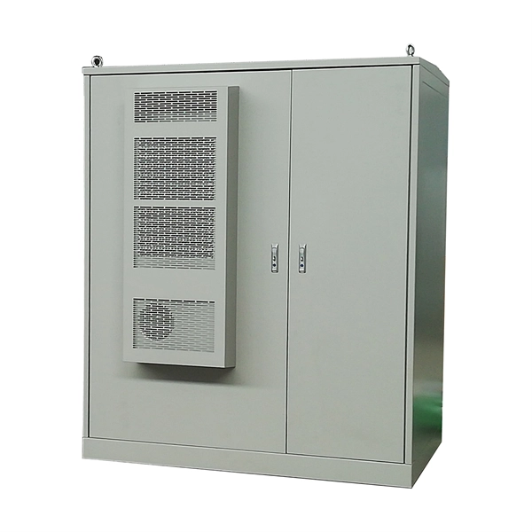
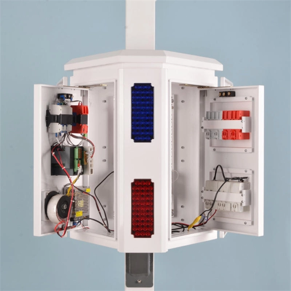
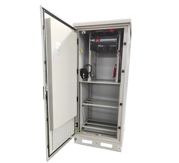
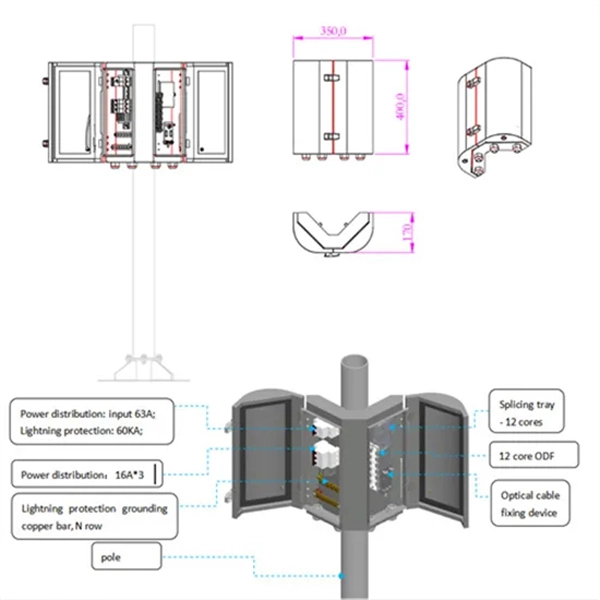
Components listed in the table need to be installed onsite. Models of the components inside the transformer station are specified by the transformer station vendor.
Understanding Fiber Rings: Key Concepts and Terminologies in Fiber Optic NetworksExplore the essential terms and concepts around fiber rings, including
Mastering the visualization of connectivity with this comprehensive guide to Ring Network Topology Diagrams. Understand what Ring Network Topology is and
A fiber ring is a network topology that connects multiple locations in a circular configuration using fiber optic cables, creating a self-healing communications loop. This architecture provides redundant
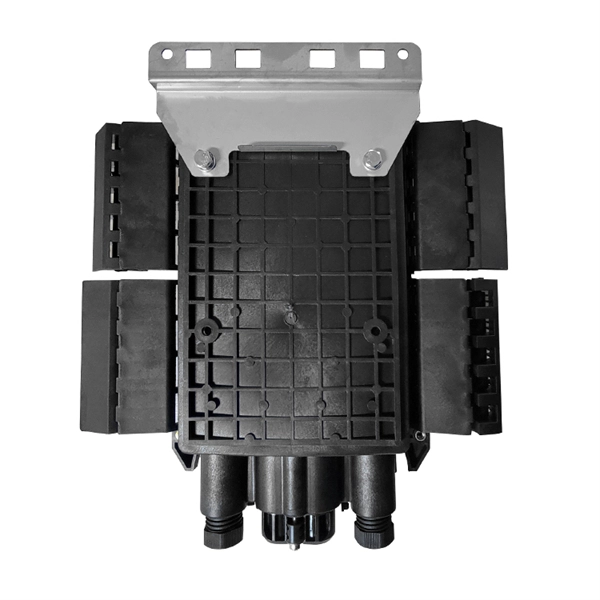
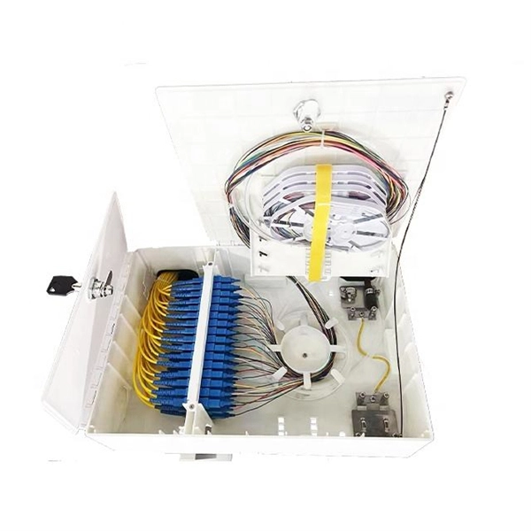
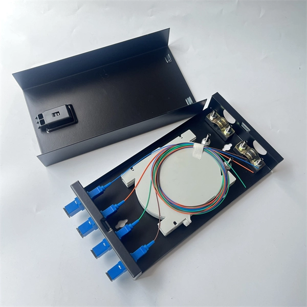
Fiber optical communication ring is a ring network which consists of multiple fiber optical termination boxes connecting hand by hand in a circle, where one node broken won''t disturb the master fiber
It is in effect a star topology achieved with a ring infrastructure. Fibre ring topology diagram In the event of one of the twelve core fibres breaking, traffic would
Fiber Optic backbones have been used effectively in industrial Ethernet systems requiring high-speed communications with excellent noise

In setting up a fiber optic wiring diagram for an IP CCTV camera system connected to an NVR using a PoE media converter, a precise and meticulous approach is crucial. Begin by identifying the
Abstract: Fiber optic network backup switches allow the users the capability of sharing a device/s connected to the COMMON port/s among devices connected to the (A, B, C, etc.) lettered or (1, 2, 3,
This application guide helps designers and installers select and deploy fiber optic media in plant environments. It details fiber optic network infrastructure solutions that provide high-performance
In fiber optic access networks, there are three main basic network topologies are bus, ring and star. However, in large networks, some hybrid
In large-scale PV projects, fiber optical communication ring can guarantee stable and secure communication which is crucial to plant''s healthy operation & maintenance.
Fiber optic connection has a world-renowned reputation for long-distance and high-performance data networking due to its inherent advantages

We provided an overview of the key characteristics of fiber optic communication system architectures and common fiber optic

Because they allow span switching as well as ring switching, four-fiber BLSRs increase the reliability and flexibility of traffic protection. Two fibers are allocated
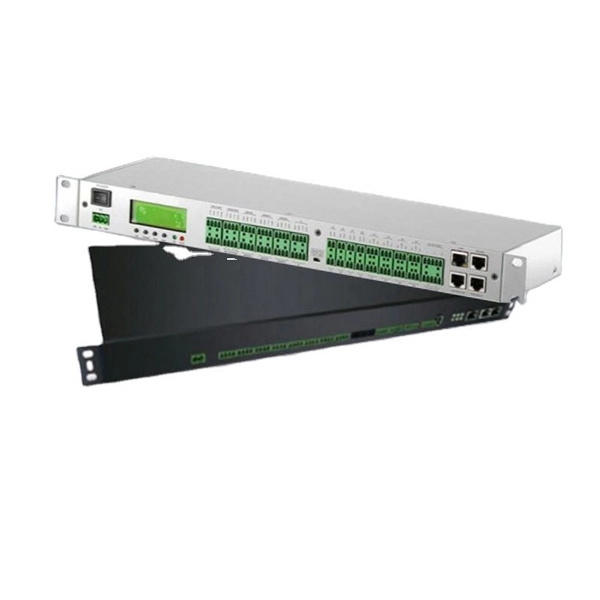
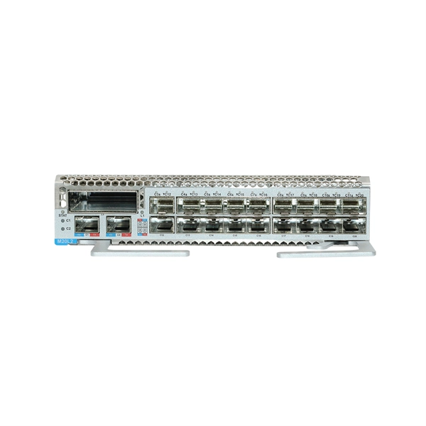
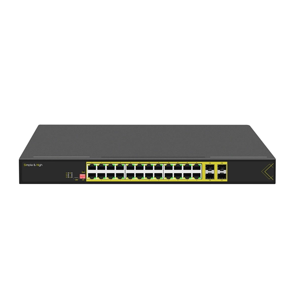
The Fiber Optic switch is used for designing an Ethernet network in loop topology. On account of the loop structure, the network is fully redundant since, in the case of an fiber rupture, it is possible to still
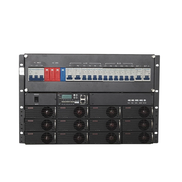
Figure 1 illustrates the interconnection between these types of networks. Networks can be configured in a number of topologies. These include a bus, with or without a backbone, a star network, a ring
Sonet Topologies1 Sonet Rings and Tcc+/Tcc2 Cards2 Bidirectional Line Switched Rings3 Linear Adm Configurations4 Path-Protected Mesh Networks5 Four Node Configurations6 Optical Speed UpgradesONS 15454 can support two concurrent BLSRs in one of the following configurations: •Two, two-fiber BLSRs, or •One two-fiber and one four-fiber BLSR. Each BLSR can have up to 32 ONS 15454s. Because the working and protect bandwidths must be equal, you can create only OC-12 (two-fiber only), OC-48, or OC-192 BLSRs. For information about BLSR protecti...See more on cisco theictguy .uk
Fibre loops, also known as fibre rings, refer to a network setup where each node or building connects to the next in a loop formation using fibre optic cables. This
Download scientific diagram | Fiber optic network with ring topology and ADM from publication: Application of fiber-optic techniques in the transport and access
This case study examines how a large photovoltaic (PV) solar farm deployed a fiber ring topology using Omnitron RuggedNet 10G managed industrial Ethernet switches to achieve high availability, long
Contact us for competitive quotes on any of our power communication and smart grid products
Get a Quote