
CPO stands for Co-packaged Optics. It refers to the co-packaging scheme in which the switching chip and optical engine are assembled within the
Why Co-Packaged Optics? Co-packaged optics (CPO) considered as a promising solution for data center interconnects ‐ Increasing traffic at data center ‐ Conventional pluggable optics facing
Schematics of active optical package (AOP) substrate: (a) cross section; (b) enlarged view of a micromirror-based optical coupler between a silicon
The CPO JDF plans to release three documents focused on different elements of Co-Packaged Optics (CPO): the optical module, the External Light Source (ELS), and the CPO assembly (covered here).
ptics (CPO) have been proposed. Fig. 1 shows the typical block diagram of a pluggable transceiver consisting of on-board lasers, optics, a Photonics die housing the modulator, the photodetector, and
From EML lasers and DSPs to silicon photonics and external CW lasers. How CPO works and the impact on the optical supply chain.
(a) Conceptual schematic of a co-packaged-optics (CPO) switch subassembly and (b) a demonstrator CPO switch system by Intel.
Download scientific diagram | a Pluggable optical module . b Architecture of CPO from publication: Co-packaged optics (CPO): status, challenges, and solutions | Due to the rise of 5G, IoT
The optical engine of a transceiver—whether co-packaged or part of a pluggable module—typically includes an electronic integrated circuit (EIC) and
Functional block diagrams for transceiver Module variants. 8. Figure 3. Cross-section of PCBA, CPO substrate, switch IC, and Optical transceiver. 9. Figure 4.
Each XPO module delivers 12.8Tbps of bandwidth using 64 electrical lanes and incorporates an integrated liquid-cooled cold plate capable of supporting 400W+ module power consumption.
In the rapidly evolving landscape of data center optical interconnects, the competition between LPO (Laser Phased-locked Oscillator)
Discover how co-packaged optics (CPO) are transforming high-speed interconnects, offering a five-fold bandwidth increase and improved efficiency.
A CPO optical module integrates optical and electronic components to boost data center speed, efficiency, and bandwidth while reducing power use.
1.1. Scope This document defines the technical specifications for a 3.2 Tb/s Copackaged Optic (CPO) transceiver module. This device will serve as a building block to enable a lower power solution for a
Introduction Co-packaged optics (CPO) is a much-anticipated revolution in the architecture of high-bandwidth switches and distributed-computing hardware used in data centers (DCs). The prevailing
Download scientific diagram | Collimated fiber array connector: (a) Alignment system schematic; (b) Assembly conceptual view. from publication: Detachable
Optics Primer, Part 3: Co-Packaged Optics (CPO) From EML lasers and DSPs to silicon photonics and external CW lasers. How CPO works and the
Ansys Lumerical and Zemax toolsets provide the best-in-class solutions to simulate and design complete optical coupling systems for co-packaged optics and other integrated photonics applications.
For the reason above, adoption of CPO which can replace some electrical paths to optical paths in the net- work switch equipment is expected. Figure 1 shows a schematic illustration of the CPO.
Co-packaged optics (CPO) are heterogeneous integration packaging methods to inte-grate the optical engine (OE) which consists of photonic ICs (PIC) and the electrical engine (EE) which consists of the
The invention relates to the technical field of optical packaging, and particularly discloses a CPO optical module packaging structure and a preparation method thereof, wherein the CPO optical module
NPO vs CPO: Compare optics placement, data speed, upgrade flexibility, and power efficiency for your data center needs.
At the same time, to achieve larger capacity and higher integration, development of optical interfaces using Co-Packaged Optics (CPO) technology, which are fundamentally different form to current
It refers to the co-packaging scheme in which the switching chip and optical engine are assembled within the same integrated socket. Figure 1 CPO
In this embodiment, a CPO optical module package structure is provided, fig. 1 is a schematic structural diagram of the CPO optical module package structure provided according to an embodiment of the
Download scientific diagram | (a) Conceptual schematic of a co-packaged-optics (CPO) switch subassembly and (b) a demonstrator CPO switch system by Intel. from publication: New trends in
This document defines the technical specifications for a 3.2 Tb/s Co-packaged Optical (CPO) transceiver module, including mechanically compatible Copper Cable Attach modules, see
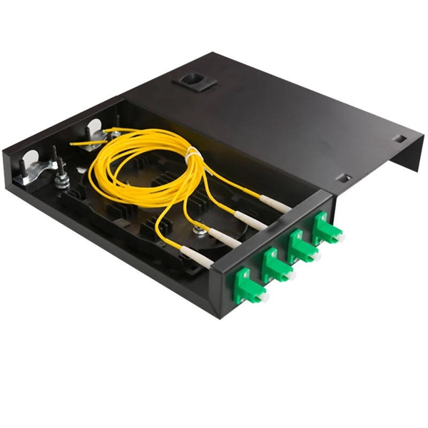
Contact us for competitive quotes on any of our power communication and smart grid products
Get a Quote