
Optical loss testing of multimode fiber can be affected by many variables, including fiber mismatch, the type and quality of the test reference cords and the launch
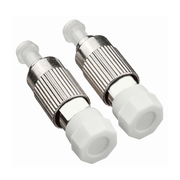
The passive fiber optic link may include the following components: 1) fiber optic cable, 2) fiber optic connectors, 3) fiber optic adapters, 4) fiber optic splices and 5) fiber optic “hardware” (housings and
Introduction to Multimode Fibers Multimode fibers are a type of optical fiber that allows multiple modes of light to propagate through them simultaneously. This characteristic enables them

Multimode optical fiber (MMF) imaging is an emerging fiber imaging technology that has been developed during the last decade. In this work, we demonstrate deep-learning-based MMF
17.3.2.2 Multimode, multicore, and few-mode fibers Multimode fibers are simultaneously an old and emerging technology within the context of optical systems. The first optical fiber systems back in the
Fiber optic testing by Fluke Networks ensures network performance and reliability. Includes signal loss, quality checks, and more.
Explore the intricacies of multimode fibers and their optical properties, and learn how they are revolutionizing the field of optical communications.
Explore OM1, OM2, OM3, OM4 & OM5 multimode fibres. Compare features, bandwidth & distances to choose the right fiber type for your network
5 OLTS – Tier 1 Measurement Principle An OLTS measures the overall attenuation of a fiber optic cabling using a light source on one side of the link and an optical
Multi-mode optical fiber is a type of optical fiber mostly used for communication over short distances, such as within a building or on a campus. Multi-mode links can
Key Parameters for Testing Multimode Fibre Optic Cables and Transmitters Principles on the measurements related to the Mode Transfer Function, Encircled Flux, and Mode Power Distribution:
There are three fundamentally different dispersive phenomena in optical fiber, of which polarization mode dispersion (PMD) is the most complex. In digital
The following section titled “Selection Considerations” requires a general understanding of multimode fiber systems testing as well as optical launch conditions.
Learn how single-mode and multi-mode transceivers differ, compatibility rules, testing tips, and best practices for reliable fiber deployments.
Buffer coating – Protects the fiber from damage and moisture Strengthening materials – Typically Kevlar fibers that prevent the cable from stretching Outer jacket – The final protective layer
Single-mode and multi-mode fiber test equipment are essential tools for those involved in the installation, maintenance, and troubleshooting of fiber optic cables. Your choice between the two
Modal Effects on Multimode Fiber Loss MeasurementsIn order to test multimode fiber optic cables accurately and reproducibly, it is necessary to understand
Singlemode fibre generally comes with a relatively narrow diameter, through which only one mode will propagate typically in 1310 or 1550nm band wavelength and carries higher bandwidth than
Using a frequency domain instrument, vector network analyzer (VNA), the method measures the complex transfer functions (CTFs) of multimode fibers for a given set of launch conditions.
We breakdown the differences between single mode and multimode fiber optic cable, covering aspects like physical structure, bandwidth over
Understand the difference between fibers: single mode offers long-distance, high bandwidth, while multimode suits short runs and lower costs.
Key Parameters for Testing Multimode Fibre Optic Cables and Transmitters Principles on the measurements related to Encircled Flux and Mode Power Distribution: Key parameters in the
Multimode fiber optic cables are essential in modern data communication systems since they can transmit data efficiently and at high
troduction This paper explains the recommended guidelines for testing an installed fiber op. ic system. Fiber optic testing of a newly installed system not only verifies that the system meets its design
Micro bending occurs when the fiber core deviates from the axis and can be caused by manufacturing defects, mechanical constraints during the fiber laying process, and environmental variations
Learn how to effectively test both single-mode and multimode fibres with an Optical Time Domain Reflectometer (OTDR). Explore tips, techniques, and the best launch and receive cables for
Mode conditioning will result in more consistent test conditions which will provide more accurate test results. For 50/125 fibers it will meet Encircled Flux (EF) standards for mode conditioning. Optical
Contact us for competitive quotes on any of our power communication and smart grid products
Get a Quote