
Here, we provide an overview of common substation busbar configurations—Single Bus, Main and Transfer, Double Breaker/Double Bus,
Ever wondered how busbars, the unsung heroes of electrical distribution, are processed and installed? This article delves into the intricate
Busbar in Electrical System: Types, Applications, Considerations, and Maintenance Electrical busbar is the most important component in power
These standards collectively form the regulatory framework for busbar design, ensuring that all design and testing
In this case, bus bar configuration might be low in profile, thereby changing the orientation of the bus structure and the airflow. Bus bars may also serve to
A busbar circuit diagram is a comprehensive visual representation of how electricity is distributed in a building or other structure. It can be used to
The smart busbar layout includes the hoisting scenario and support-mounting scenario. Hoisting installation starts from the first cabinet. Support-mounting installation starts from the position
Power distributed in switchboard Power is distributed in switchboards through the following means: A main busbar that distributes power
These guidelines govern the busbar processing and installation procedures for all low-voltage switchgear and power distribution enclosures
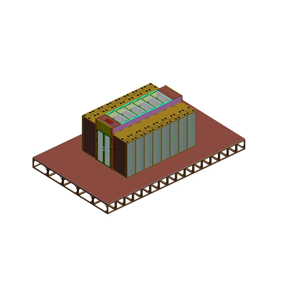
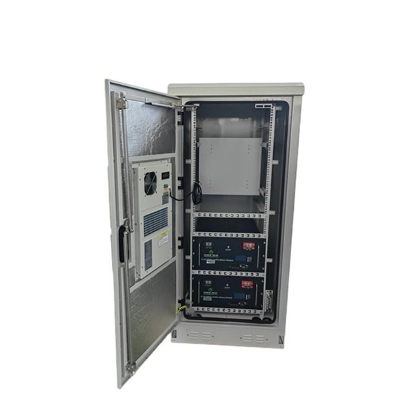
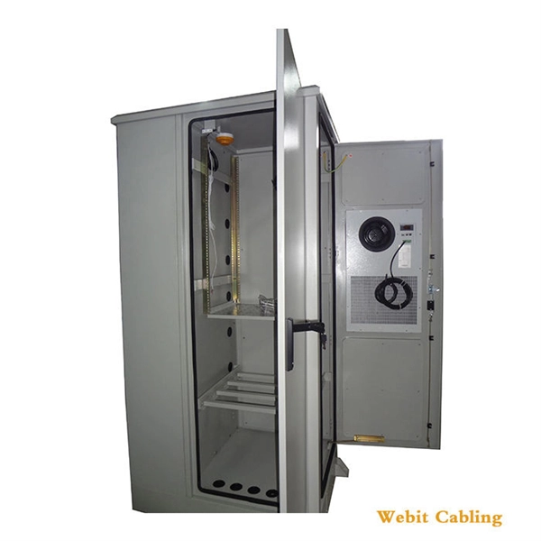
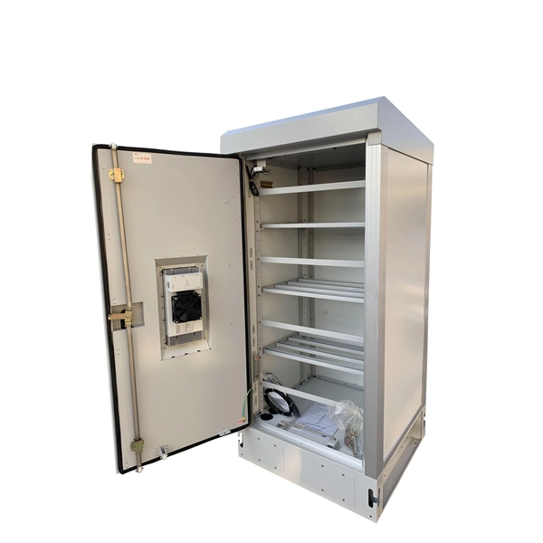
The document contains diagrams showing the layout of busbar chambers, lifting hooks, and control panels on the front and sides of an electrical equipment
Bus bar wiring diagrams are a specific type of schematic diagram designed to show exactly where each section of the circuit is connected to the
Visualize the layout using a panel diagram before mounting. Secure Installation: Firmly attach busbars using mounting brackets and screws to prevent movement and potential electrical
Discover how proper cabinet design and busbar systems improve airflow, safety, and maintenance. Learn best practices for clean, reliable power distribution layouts.
Understand Types of Busbars and how they make complex power distributions simpler in electrical power distribution,.
Impedance In the design of laminated bus bars, you should consider maintaining the impedance at the lowest possible level. This will reduce the transmission of
The document discusses different bus-bar arrangements in electric circuits including single bus-bar, sectionalized single bus-bar, main and transfer bus,
Our busbar systems for electrical installations offer a particularly easy way of fitting distribution systems with electrotechnical components. The modular design saves space, while quick assembly contacts
This document provides details on substation layout and busbar arrangements. Part A discusses substation layout, including a single line diagram and descriptions
1.1 Definition of a busbar In battery packs for electric mobility, a busbar is used to connect battery cells or modules. In automotive battery packs, busbars are used to connect battery modules together.
The system and cubicle dimensions as well as the degree of protection, rated nominal currents, ambient conditions, power loss, representation of the exact system layout including the top mounted units on
Substation Busbar System Overview The document discusses different types of busbar systems used in substations: 1) Single line diagrams provide a graphical
Typical Busbar Sizes If this program recommends sizes that do not fit into the ranges below, change either the number of conductors or the section thickness of the busbar and recalculate the minimum
System Overview The MaxSB low voltage switchboard is designed, constructed, and tested to provide superior power distribution, protec-tion, and power monitoring and control. MaxSB is designed to
Take you through the entire installation process, from understanding bus bars to choosing the right type, ensuring safety, step-by-step installation, and long-term maintenance.
What Is A Substation?Types of SubstationsBusbar ArrangementsSingle Busbar SchemeMain and Transfer BusbarDouble BusbarDouble Main and Transfer Busbar SchemeMesh Busbar SchemeBreaker and A Half SchemeElectrical Layout DrawingsIn this scheme, there are two main busbars with an additional transfer busbar. When a circuit breaker is out for maintenance, its load is transferred to the transfer busbar and controlled through the bus coupler, without affecting the other feeders.See more on instrumentationtools Free CAD Block And AutoCAD Drawing
This AutoCAD DWG file provides a complete Electrical Single Line Diagram (SLD) of the MSB, along with a detailed panel layout, including circuit breakers,

In this article, you will learn about the types of electrical busbar arrangements and layout diagrams in substation.
Contact us for competitive quotes on any of our power communication and smart grid products
Get a Quote