
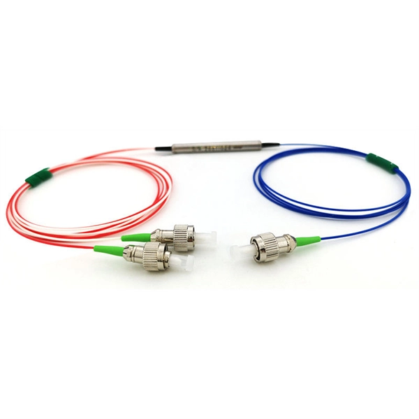
Coupler fabrication techniques include the fused biconical taper method and various multiport coupler designs are discussed. The document provides details on
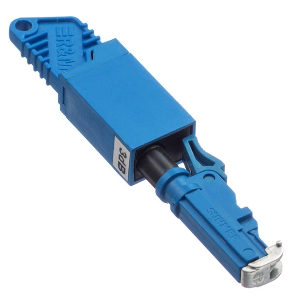
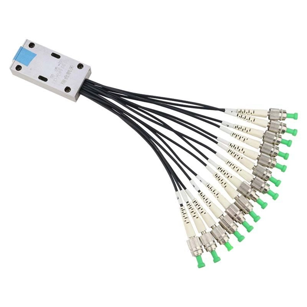
Connectors are mechanisms or techniques used to join an optical fiber to another fiber or to a fiber optic component. Different connectors with different characteristics, advantages and disadvantages and

Nowadays fiber optic cables are used extensively in network communication and unlike a normal wire joint there are some special joints for
7.10 The 36 kV joints should be suitable for use with the following type of cables : 18/30 kV, three / one core, underground power cable, Aluminum/ Copper stranded-compacted circular conductor, extruded
12.2.1 Fiber optic cable assemblies should not be combined in the same wiring bundle as wire or coaxial cable assemblies to ensure they are not exposed to handling practices that are acceptable for

Joints are used to transfer light from one fiber optic cable to another and are made up of plastic or glass materials. In this article, we will explore the various types of joints in optical fiber.
7.3.2 Cables (see Figure 7-1 for a typical fiber optic cable) shall be prepared for termination in a fashion that will allow for the fiber to be exposed without sustaining damage or contamination.
In addition, this Recommendation advises on the optical, mechanical and environmental characteristics of the splices and advises on suitable testing methods. Further information is provided in the CCITT
This document specifies the minimum technical requirements for design, engineering, construction, manufacture, inspection, testing and performance of fiber optic connectivity components, consisting
Fiber optic cable must be protected in intermediate manholes. Carefully choose racking space so that it will provide maximum protection for the cable and maintain its minimum bend radius.
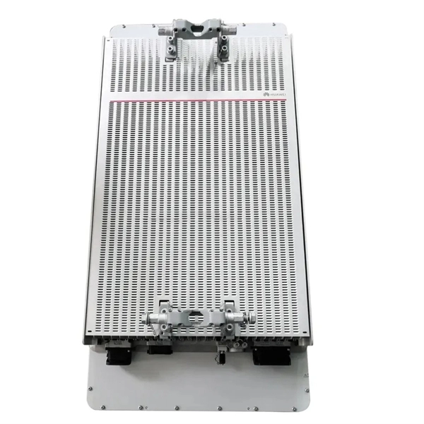
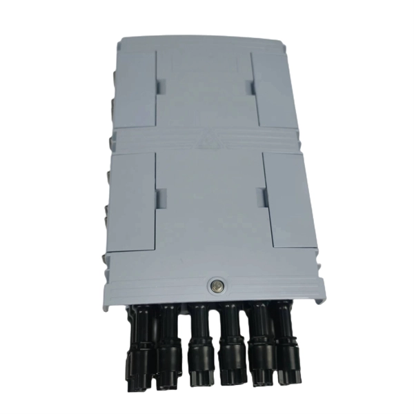
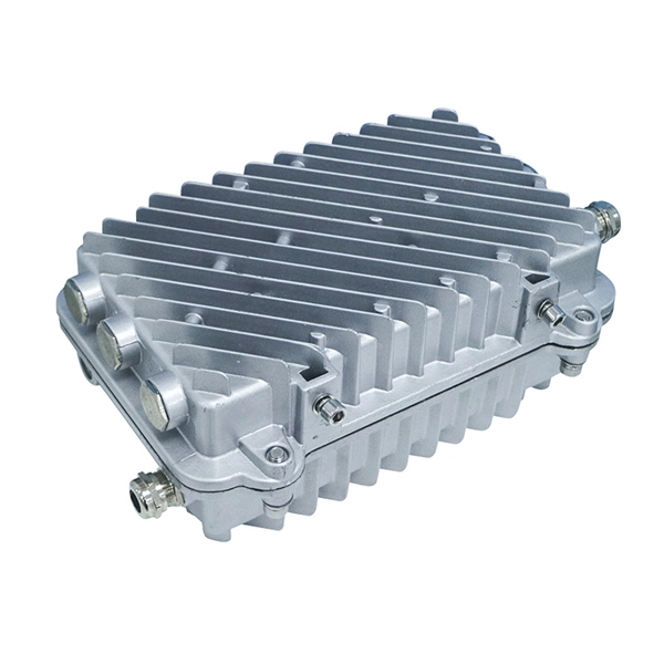
They are specially designed for track, spur and loop applications due to the compact sizes and fibre capacities, and ideal for use as Cable Chamber Joints, Track Joints, Spur Joints or Distribution Joints.

Performance of optical fibre cable is inversely proportional to the numbers of joints throughout its route as every joint increases signal losses. We ensure that this handbook will help to field staff in
Prysmian has a comprehensive portfolio of joints to manage the splicing and distribution of optical fibres throughout the network in both point-to-point and
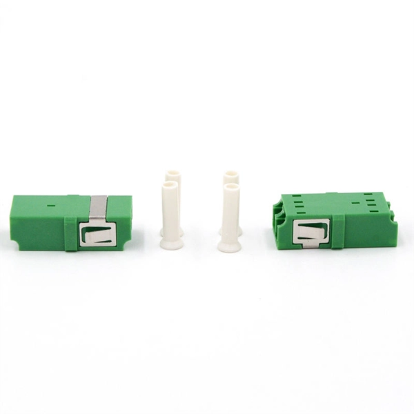
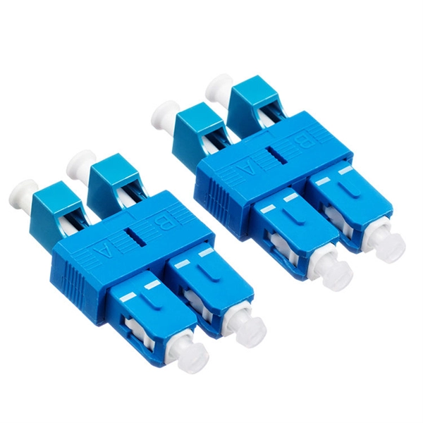
IEC fiber connector standards establish the global specifications for connector geometry, mating interfaces, optical performance classes, and
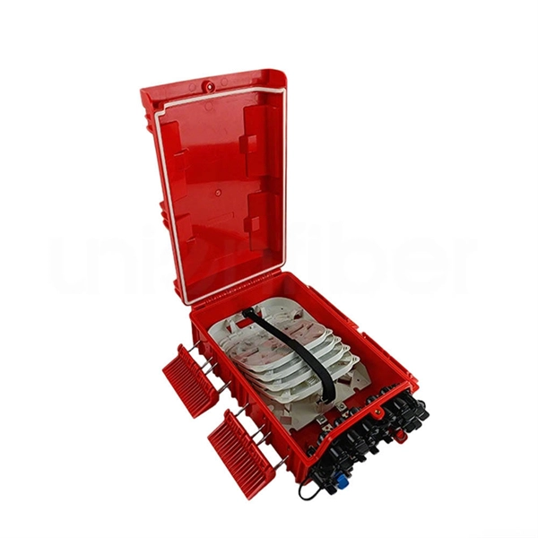
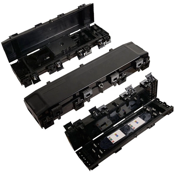
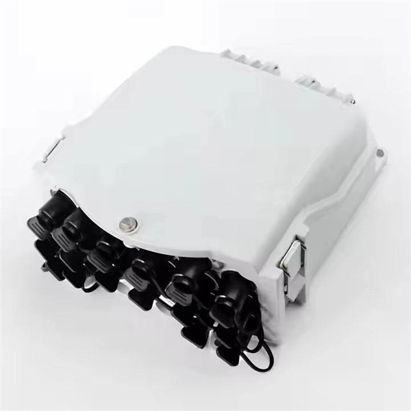
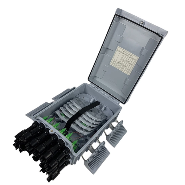
Technical Specification Optical fiber cable joint closure mainly consist of a moulded shell pipe (pipe shaped with one end closed) with an end cap having parallel ports and oval port for the cable entries

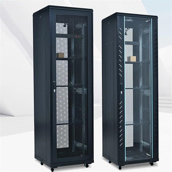
Moreover, the optical plant needs a lot of complementary hardware (passive nodes, optical distribution frames, joint closure, cabinets, etc.), which needs a detailed development and specification both for
cation of optical fibres in cables and associated characterization methods. F r each recommendation, several types of fibres (subcategories) are offered. These documents are available free of charge on
(i) Mechanical Splice - These are the joints that mechanically hold the two fiber ends and are just an alignment device enabling light to pass from
Fiber optic joints or terminations - where cables are terminated - are made two ways: 1) connectors that mate two fibers to create a temporary joint and/or

The document discusses methods for joining optical fibers, including fusion splicing and mechanical splicing. Proper preparation of the fiber ends is important for

Common connector types are named FC, SC and LC for single-mode applications and ST for multimode, but there are also dozens of other types, with special qualities such as duplex
Contact us for competitive quotes on any of our power communication and smart grid products
Get a Quote