
Learn how much spacing should be between brackets when installing cables in walls, ceilings, and tight spaces. Tips for secure and compliant cable bracket installation.
The spacing stated for horizontal runs may be applied also to runs at an angle of more than 30 Degrees from the vertical. For runs at an angle of 30 Degrees or less from the vertical, the vertical spacing is
A practical guide to product selection and installation This guide for engineers and installers has been developed by ABB as a practical reference regarding cable tray characteristics, installation, and
This guide covers the critical steps, from selecting the right electrical cable tray and performing accurate cable fill calculations to managing a safe cable pull through
Introduction This publication is intended as a practical guide for the proper and safe* installation of cable ladder systems, cable tray systems, channel support systems and associated supports.
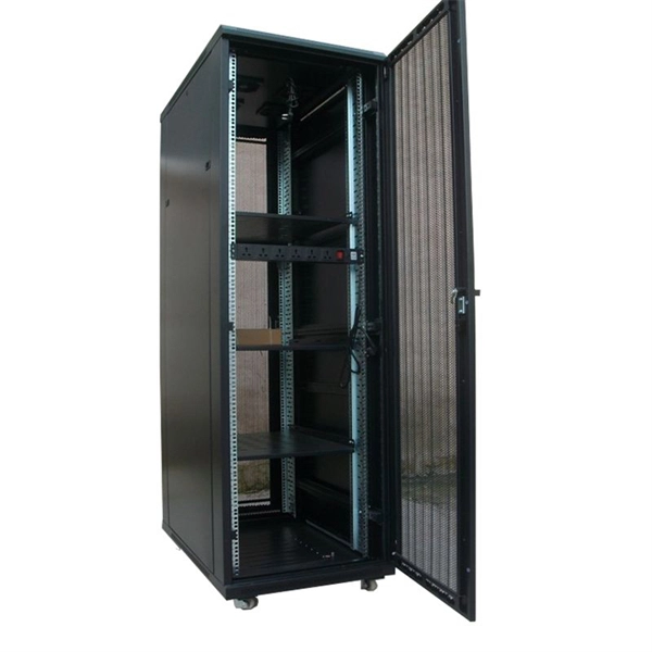
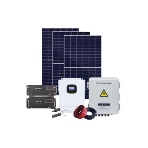
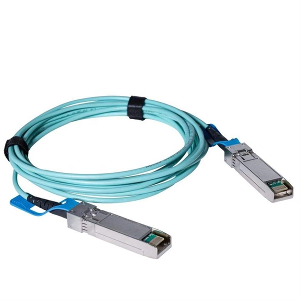
FEATURES Supports horizontal/vertical and overhead cable management Durable black or gray powder coat finish Supports UTP or fiber cabling Complete family of accessories includes: wall supports and
The document outlines steps for laying cables, including installing supports, fixing the tray, laying cables with proper spacing, and tying them with cable ties.
When planning the vertical spacing between floor-mounted cable trays, the minimum distance should be 150 millimeters. This clearance prevents potential obstruction and ensures the
The mesh cable trays are suitable for the installation of power cables and cables in various areas of application. The grid spacings mean that cables can be inserted and run out in various directions.
As per the NEC, the maximum allowable rung spacing is 9 inches (230 mm) when cable tray carries sin-gle-conductor cables of 1/0 to 4/0 AWG (American Wire Gauge) (Appendix I).
In accordance with its continuous impro-vement policy, Legrand reserves the right to change the specifications and illus-trations without notice. All illustrations, descriptions and technical information
Proper installation is not just about placing the cable tray in the right position; it also involves correct selection and layout, ensuring structural safety, maintaining
The 2026 NEC introduced an important update: cable trays must have at least 12 inches of clear vertical space above them to allow for installation and maintenance access.
Cable tray system shall be used for laying of MV and LV power, control, instrumentation and special cables in the Power Plant. Cable trays shall be
For Cable Tray Installers—This publication is intended as a practical guide for the proper installation of cable tray systems. Cable tray systems design shall comply with NEC Article 392, NEMA VE 1, and
Installation of Cable in Cable Trays ensures proper routing, cable management, NEC compliance, grounding, fire safety, and load capacity.
All cables should therefore be suitably supported. When the cable is installed ''clipped direct to a surface'', then the clipping distance should be in line with the IET Selection and Erection Guidance
This method statement covers the site installation of the cable tray & ladders and the requirements of checks to be carried out.
Wall support brackets (Figures 12) are an effective way of fixing any width of cable ladder or cable tray, running either vertically or horizontally, to a vertical support.
Installation Environment: Consider the installation environment, including factors such as vibration, wind load, and temperature fluctuations, which can affect the stability of the cable tray system. In harsher
Cable tray systems are to be installed so they are accessible. If possible 300mm minimum should be left above or between installed systems to allow for cable
5. Cable tray installation shall preferably be installed flat in buildings or operating structures. Tray shall run as far as possible under flooring and
Any horizontal and/or vertical change of direction can be realized on site with the fittings and the connectors (from page). All changes of direction must be
The following recommendations are intended to be a practical guide to ensure the safe and proper installation of cable ladder and cable tray systems and channel support and other support systems.
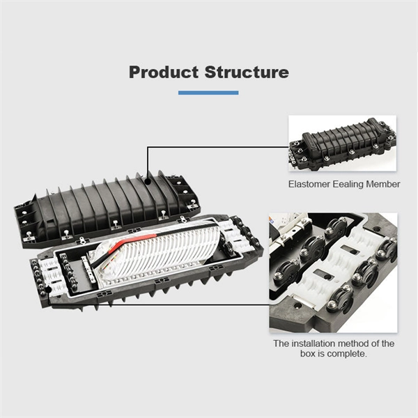
(8) When the cable is laid vertically in the cable tray, it should be fixed on the bracket of the tray at the upper end of the cable and at every interval of 1.5 meters. fixed at the meter.
In vertical installations, the weight of the suspended cable creates a tensile load on itself and is the factor, from a cable perspective, that limits the height of vertical installation for a tight buffer cable.
Cable support systems are generally designed with at least 50 % reserve space available for each tray. Cable tray types, supports (types and spacing) and securing systems are selected and designed
Cable ladder and cable tray systems The following recommendations are intended to be a practical guide to ensure the safe and
Contact us for competitive quotes on any of our power communication and smart grid products
Get a Quote