
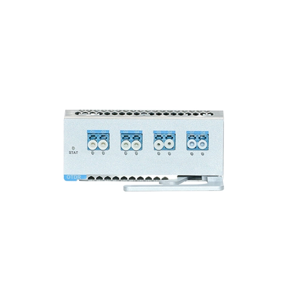
important. The OTDR trace can be used for cable acceptance, splice and connector loss, documentation, troubleshooting, fault location, optical return loss, and to measure the length of PM
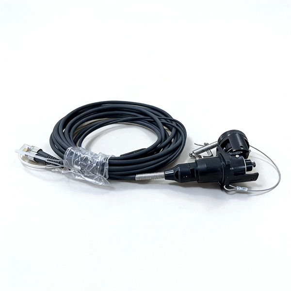
For insertion loss testing, this requires reference launch jumper cables to connect the test source to the fiber in the cable under test and receive cables to connect
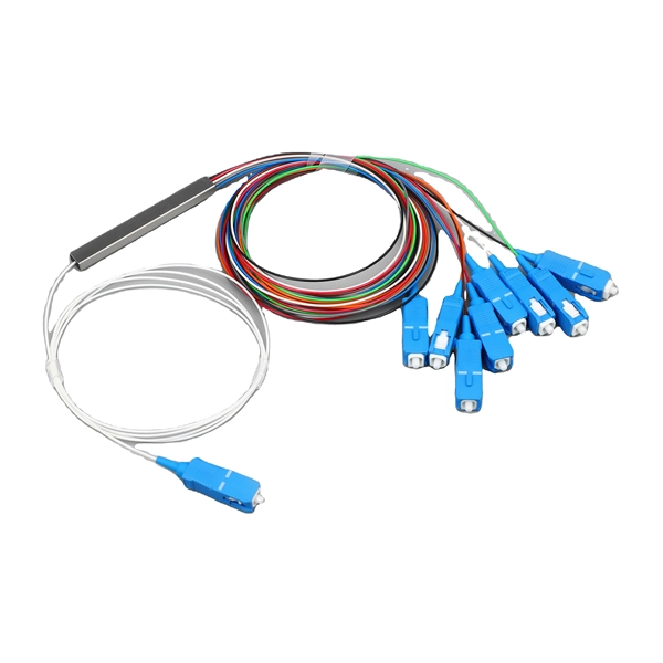
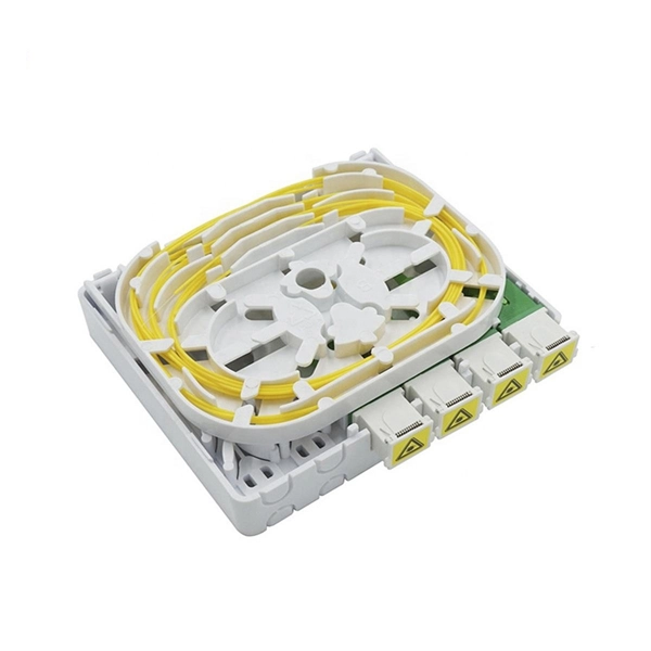
Insert loss of fiber jump line,Introduction:Fiber optic jumpers, also known as fiber optic patch cords or cables, are used to connect two or more
Optical Fault Finders Advanced Troubleshooting with Optical Time Domain Reflectometers (OTDR) Launch And Receive Cables and Compensation
Fiber optic jumpers, especially ceramic ferrule jumpers, are also critical in the telecommunications industry because they support high-power
Measuring the insertion loss of a Single Mode jumper would seem simple but there are a few complications to consider, which we cover in this article.
The one-jumper reference method is your go-to technique for accurately testing fiber optic links that terminate in connectors at both ends. It''s recognized by industry standards like TIA-568 as the most
In fiber-optic communication, a single-mode optical fiber, also known as fundamental- or mono-mode, is an optical fiber designed to carry only a single
INTRODUCTION Fiber optics has been providing long distance connections for a long time. But, until now, the higher cost often made it
Accurate measurement and testing in fiber cable installation are crucial to ensure overall network integrity and performance. A significant signal
Fundamentally, Insertion Loss is the loss of power that results from inserting a cable into a network or transmission path. Keep in mind that, inevitably, some power is lost because every
Conclusion In summary, fiber patch cables are essential components in modern communication networks. They are used to transmit data, video, and
A reference wire is required to connect to the fiber cable under test – one end is called the “emission” reference line, from the light source to the
For fiber jumper suppliers, the insertion loss and return loss of the fiber cables they provide should meet the corresponding standards. The max insertion
While there are many different fiber optic cable tests, the most common version is an insertion loss test, also known as an attenuation, jumper, or connectivity test. This test requires a
Optical fiber broadband brings together a culture of innovation, quality, and manufacturing excellence to create life-changing products.
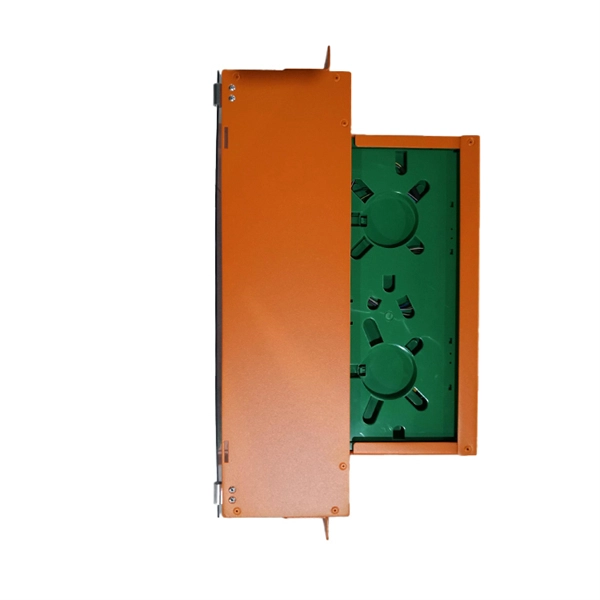
Insertion Loss (Connector, Splice & Link) The passive fiber optic link may include the following components: 1) fiber optic cable, 2) fiber optic connectors, 3) fiber optic adapters, 4) fiber optic
Referencing Jumpers for Systems with SC/UPC and OptiTap Connectors: The following steps describe referencing jumpers for power-through testing an FTTX system consisting of an
The 1-jumper reference provides the least uncertainty by accounting for the loss of both end connections. The 2- and 3-jumper methods offer less accuracy or incomplete loss measurements.
To measure the insertion loss of a single-mode fiber optical device, follow these steps to ensure accuracy and reliability: 1. Preparation Fiber Optical Jumper
Guidelines On What Loss To Expect When Testing Fiber Optic Cables To be able to judge whether a fiber optic cable plant is good, one does a insertion loss test
Optical fiber is a fantastic medium for propagating light signals, and it rarely needs amplification in contrast to copper cables. High-quality single mode fiber will
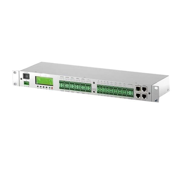
Optical Loss Test Sets (OLTS) help network and data center administrators ensure fiber links stay within budget and provide expected
What is Insertion Loss? Insertion loss is the amount of energy that a signal loses as it travels along a cable link. It is a natural phenomenon that
The 3-jumper method references out two connectors and therefore excludes the loss of both end connections to the cabling under test. The 1-jumper method is the only method that includes the loss
In optical fiber communication systems, a jump fiber is used to connect two optical fibers together. The process of joining two optical fibers is called splicing, and it involves melting the ends
They are an essential component of fiber optic communication systems, enabling high-speed data transmission over long distances. In this
Single-port, simultaneous dual-wavelength feature completes testing in half the time and saves measurements from both wavelengths into
Contact us for competitive quotes on any of our power communication and smart grid products
Get a Quote