

Some applications may require the cable tray to support the weight of a single, dead object in addition to the cable loads. Specifications typically require this to be applied at the midpoint of the span between
Learn common methods for connecting cable trays safely and efficiently. Our guide covers splice plates, quick-connects, and key tips for
Standard Support Construction Of The Cable Tray RS With the RS 60 cable tray installation system, we offer you the last installation type of the standard support
Armorduct cable tray systems are usually assembled using M6 roofing bolts particularly for couplers, fishplates and connection to supporting framework. It should be noted that independent testing has
The cable trays are fastened to the cantilever brackets with 2 mushroom head bolts (FLM 6X12/FLM 6X16 F). The threaded rod can also be fastened directly to the
ADVANTAGES OF CABLE TRAYS cable tray systems are manufactured in accordance with the precise standards laid down by the National Electrical Manufacturers Association (NEMA).
Standard length of 3, 4, and 6 meters Channel cable tray is used for installations with limited numbers of tray cable when conduit is undesirable. Support
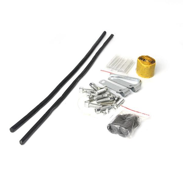
• For connecting two straight sections of cable tray (Hardware included) • Available as a standard nut and bolt • Sturdy design for heavy load weights • Professional
A practical guide to product selection and installation This guide for engineers and installers has been developed by ABB as a practical reference regarding cable tray characteristics, installation, and
NEMA VE 1-2017 Specifies requirements for metal cable trays and associated fittings designed for use in accordance with the rules of Canadian Electrical Code, Part I and the National Electrical Code®
MP Husky manufacturers Cable Tray Systems, Cable Bus System, Wire Mesh/Wire,Cable Tray, & Cable Management Systems. Our cable support
This standard outlines the construction requirements, testing methods, and performance parameters for cable trays and related support
2 manufacturer as the cable trays. These auxiliaries shall be from the standard range of products of the manufacturer. Each length of cable tray shall be supplied with a set of joining pieces, bolts and nuts
The fittings can fastened to the cable tray rail either with double clamps of type DOP A2 or with truss-head bolts of type FRS and combination nuts. The exceptions to this are vertical bends, adjustable
This publication is intended as a practical guide for the proper and safe* installation of cable ladder systems, cable tray systems, channel support systems and associated supports.
This standards publication was developed by the NEMA Metal Cable Tray and Nonmetallic Cable Tray Sections. Section approval of the standard does not necessarily imply that all section members voted
Normally, fittings of up to 300 mm width are mounted on cable trays with the WKV angle connectors supplied. Fittings with a width of 400 mm or more have a connector perforation and are mounted on
IEC 61537 is the internationally recognized benchmark for metal cable tray systems. It applies to cable trays made of steel, stainless steel,
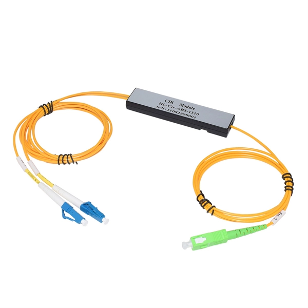
SFSP wire Basket Trays have a fast connection profile for installations requiring long runs of straight Cable Trays lengths. Applications : Network cabling, wiring closets, fiber-to-desktop applications and
Cable tray systems, including trays, supports, fittings and other materials, are generally much less expensive than conduit wiring systems. In addition, major cost savings are generated by the relative
These documents: ANSI/NEMA VE-1, Metal Cable Tray Systems; NEMA VE-2, Cable Tray Installation Guidelines; and NEMA FG-1, Non Metallic Cable Tray Systems, are an excellent industry resource in
1. The document outlines codes and standards that must be followed for design and construction of cable trays and their components. Standards listed include those
This guide covers cable ladder systems, cable tray systems, channel support systems and associated supports intended for the support and accommodation of cables and possibly other electrical
Cable Tray Systems Guide HUBBELL Hubbell Wiring Device-Kellems and Hubbell Premise Wiring are divisions of Hubbell Incorporated, a U.S. headquartered manufacturer with over 130 years of
Attaching a channel cable tray by using the method illustrated in Figure 3-88 maintains the electrical requirements, and the bolted mechanical connection while providing a practical method for dropping
In accordance with its continuous impro-vement policy, Legrand reserves the right to change the specifications and illus-trations without notice. All illustrations, descriptions and technical information
Discover over 100 expert answers about cable trays, covering key topics like material selection, load capacity, installation methods, and maintenance.
Contact us for competitive quotes on any of our power communication and smart grid products
Get a Quote