
A network switch wiring diagram is a visual representation of the connections and components that make up a network switch. It provides a clear and organized view of how devices are connected,
Switches usually have a variety of ports, including electrical and optical ports. In this video, we will introduce the concept of electrical and optical port...
Switch box wiring or switchboard wiring is a common wiring arrangement used in most house electrical wirings or switchboards. The given
There are two main port types: optical and electrical. The following information outlines the differences between switch optical ports and electrical
Explore the fundamentals of optical switching, including space, wavelength, time, and hybrid switching techniques. Learn about core components and applications.
The optical port and the electrical port of the industrial Ethernet switch are the same purposes, both play the role of transmission, the electrical
Optical Fiber Connection: The first component shown in a Fios ONT wiring diagram is the optical fiber connection. This represents the incoming fiber-optic cable that

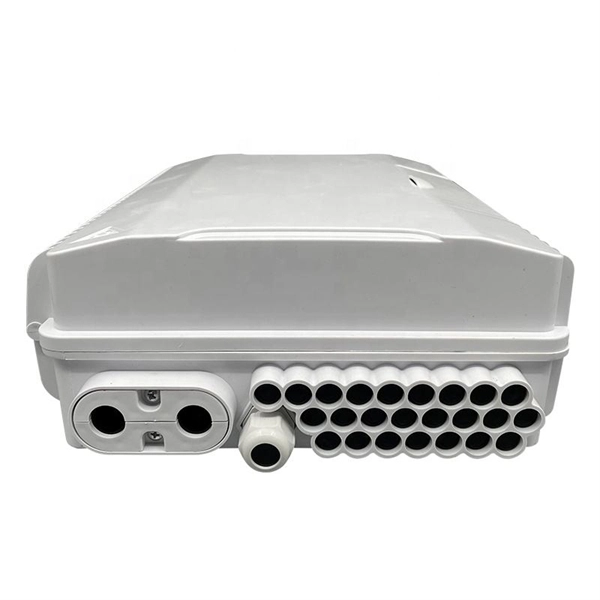
Switch port mapping diagram provides a visual representation of the network ports and their connections on a switch, aiding in network troubleshooting and management.
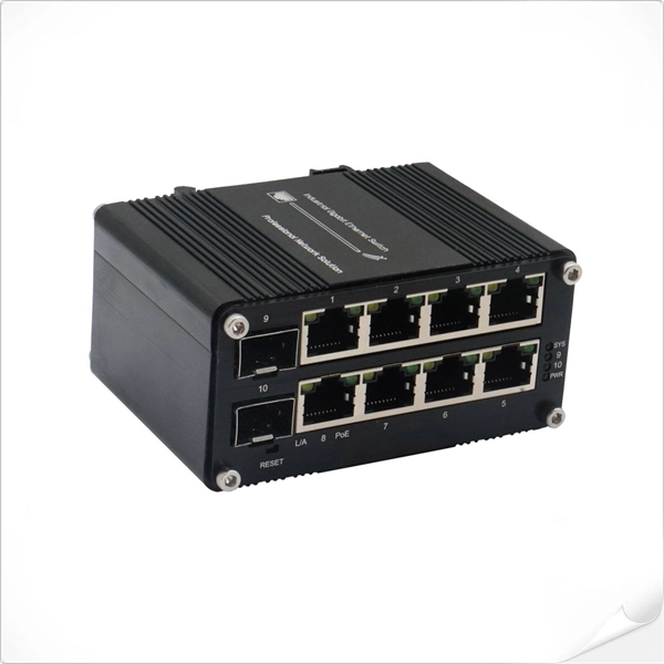
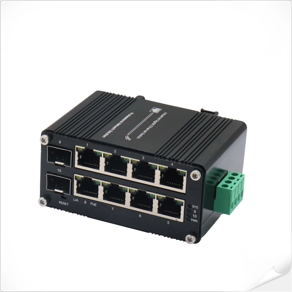
The following figure shows an example of RJ45 and SFP connections in a Gigabit Ethernet switch. On the left is the SFP connection method for UniFi switches,
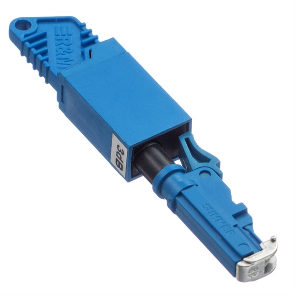
Block Diagram 1: Example of an A/B switch. The QuickSwitch® Model 4184 Fiber Optic SC Duplex A/B Switch with Remote Port enables the user to push a button for local control, or utilize the RS232

Our products and solutions optimize data transmission and network management. Explore how our hardware, software, and services can help you.

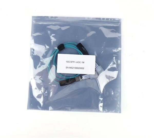
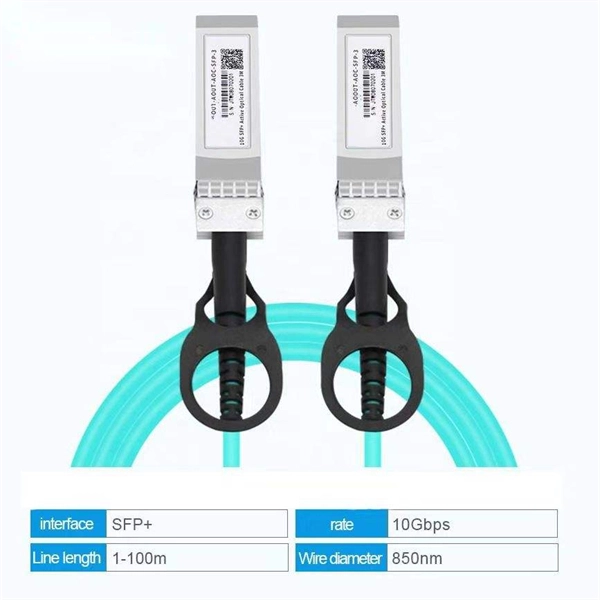
SFP Port People also call the SFP port, or small form-factor pluggable, a mini-GBIC. The SFP port is commonly found on Gigabit Ethernet
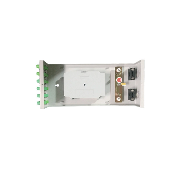
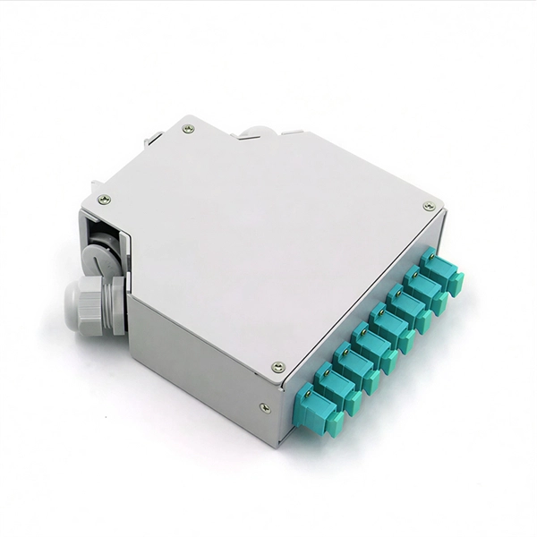
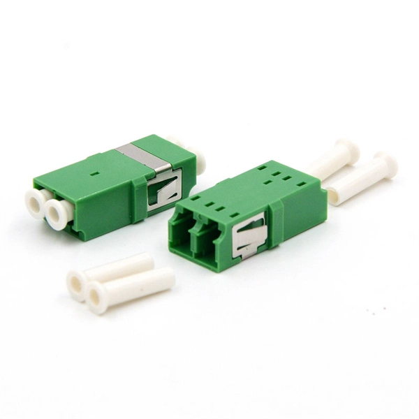
Common optical module interfaces are LC, SC, and MPO interfaces. The electrical port is also known as the cable interface (RJ45). The electrical
All-Optical Switching Tutorial, Part 1 A down-to-earth description of all-optical switches * What they are* What they do* How they work
The PON technology is based on the ITU-T G.984 standard. PON transmits Ethernet, Asynchronous Transfer Mode (ATM), and Time Division
Collection of wiring diagrams for data networks: Ethernet, fiber optics, serial connections and bus topologies. Step-by-step schematics and component
Next connect fiber cable to the SFP module. Finally, use Ethernet patch cord to link the media convertor to PoE switch. While SFP slot are not available on both

When it comes to optical ports, we can''t help but mention GBIC and SFP. What is SFP? Is the SFP optical module. GBIC is an interface
After completing the pre-installation preparations as described above, power off all devices and connect the fiber optic media converter to Ethernet devices according to the specified network topology.

Learn how to easily understand and use a wiring diagram for a switch to simplify your electrical projects and ensure safe connections.
Understanding Ethernet switch diagrams is crucial for anyone managing or troubleshooting a network, big or small. These diagrams are like
Learn how to wire an Ethernet switch with a helpful diagram. Understand the different connections and cables for a successful setup.
Explore Optical Network Terminals (ONT), their functions, and how they support efficient, high-speed connectivity in modern fiber networks.
Learn about network switch connection diagrams and how they can help you understand the layout of your network and troubleshoot issues.
Combo ports feature both electrical (RJ45) and optical (SFP) connections that are logically multiplexed, meaning only one type can be used
A switching loop or bridge loop occurs in computer networks when there is more than one Layer 2 (OSI model) path between two endpoints (e.g., multiple
A lot of customers in the purchase of industrial Ethernet switches will ask how many optical and electrical ports of switches, but also will ask what the
Fiber optic media converter circuits are a crucial component in any fiber optic network. The circuitry is responsible for connecting two networks
Contact us for competitive quotes on any of our power communication and smart grid products
Get a Quote