
1.1 Scope: This Grounding Standard describes factors affecting the ground resistance and the method of measuring ground resistance of Distribution installations.
Where continuity of service is a high priority, high-resistance grounding can add the safety of a grounded system while minimizing the risk of service interruptions due to grounds.
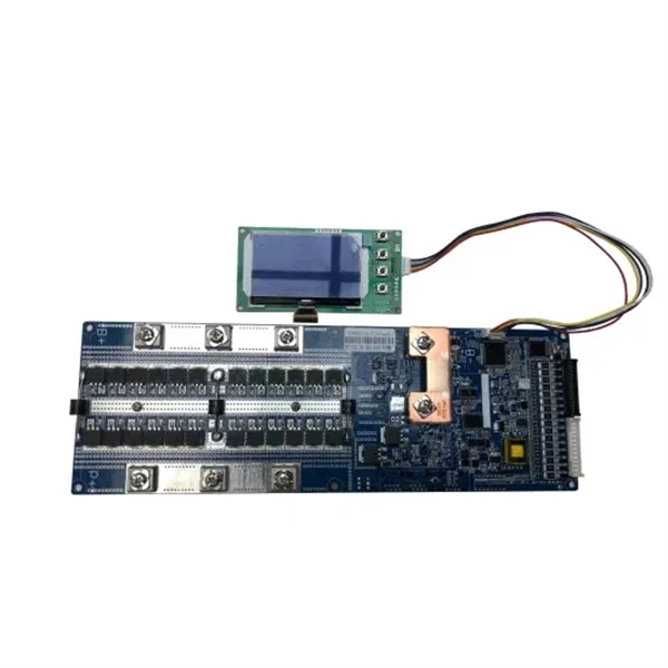
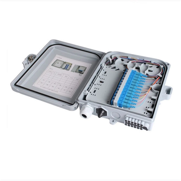
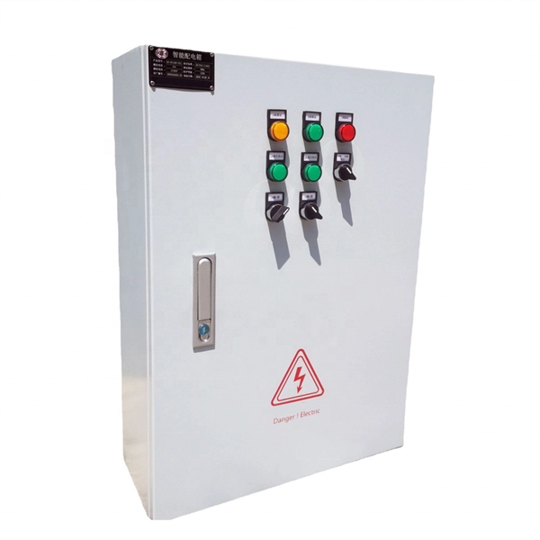
Learn what an electrical distribution box (DB/distribution board) is, its main components (MCB/RCCB/RCBO, SPD, busbar) and common types.
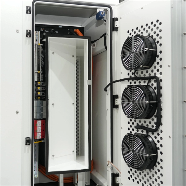
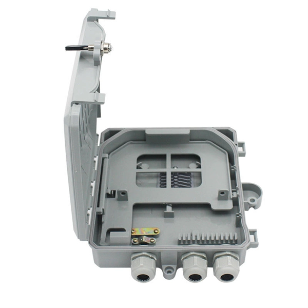
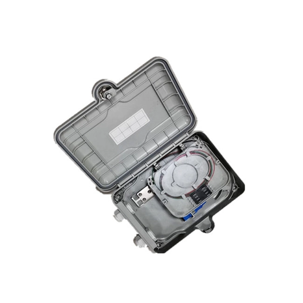
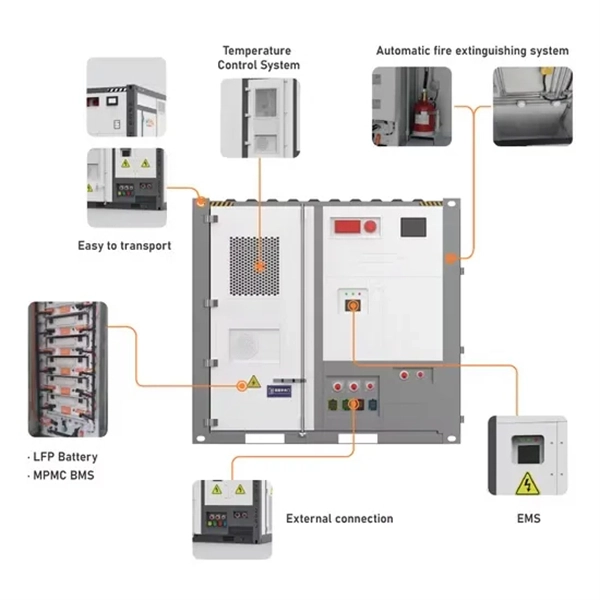
Attach a second grounding wire from the mounting plate (B), to the factory central grounding point. The ground resistance between all system parts shall be < 0.1 Ohm. Depending
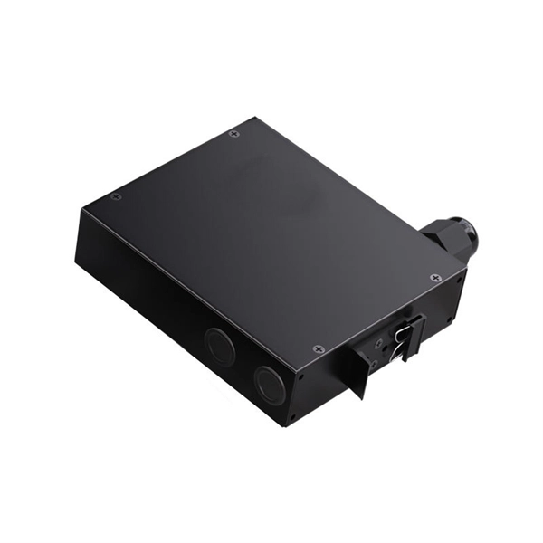
A single phase distribution box controls and protects home or office circuits. Learn its definition, main parts, and how it ensures electrical safety.
Neutral grounding, the system frequency and soil resistivity impact modeling of the distribution system components. National Electric Safety Code (NESC) is designed for primary part
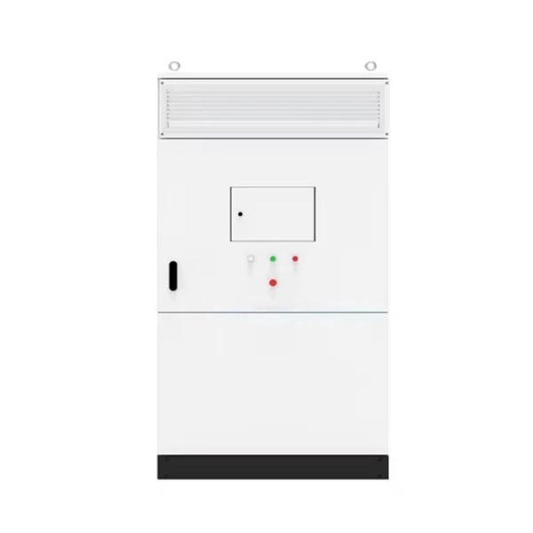
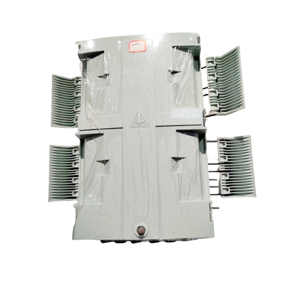
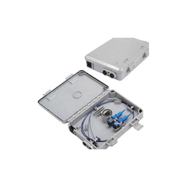
Open the distribution box and find the position marked with the grounding plate or PE letter. This position is the connection point of the
Distribution System Grounding Fundamentals Edward S. Thomas, PE - Senior Member Richard A. Barber - Member Utility Electrical Consultants, PC Raleigh, NC 27601 Abstract - The most common
Each Power Circuit Breaker or Power Transformer having a bushing Voltage Transformer on the tank shall have the Voltage Transformer provided with a separate ground lead, independent of the
will open to start the export process. The process may take but once it finishes a file will be downloadable from your browser. You may continue to browse the DL while the export process is in

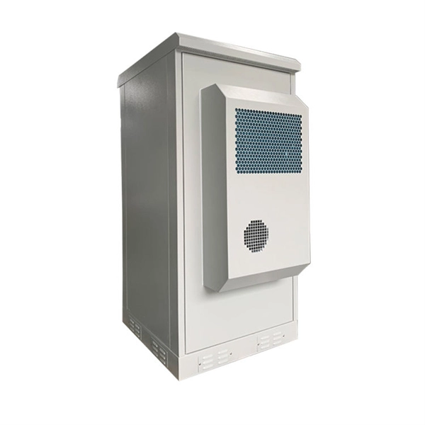
An electrical distribution box is a centralized unit responsible for distributing electrical power across multiple circuits within various
Good system grounding provides the path for normal load and fault currents while maintaining load and controls temporary overvoltages. Good equipment grounding ensures personnel safety.
Fault Current Management: In fault current management, grounding serves as a low-resistance path for fault currents, thereby guaranteeing that protective
Learn about grounding practices on distribution transformers. Discover whether the primary side is always grounded. Explore return paths and bonding between
By being connected in parallel with the customer distribution service entrance ground, any existing water system grounds will greatly reduce the effective ground electrode resistance of the average customer
Comparing Fault Resistance Coverage of Different Distribution System Grounding Methods Daqing Hou, Schweitzer Engineering Laboratories, Inc. ial plants use many types of
The article discusses the importance and purpose of grounding in utility power transmission and distribution systems, focusing on how grounding
Power transmission and distribution systems are earthed for electric shock and fault protection. This chapter presents the principles and practices of grounding for power systems. An
Ground fault current magnitudes depend on the system grounding method. Solidly- and low-impedance grounded systems may have high levels of ground fault currents. These high levels typically require
Further, the solidly-grounded neutrals allow for ground currents to flow that can create interference in communications circuits (see Electric Power Distribution System Design, New York3
Since grid resistance is viewed as a measure of the grid''s ability to disperse ground fault current, many designers are tempted to use resistance as an indicator of relative safety of a ground mesh.
The solidly-grounded and low-resistance grounded systems can also be implemented by using a grounding transformer, depending upon the amount of impedance connected in the neutral.
Good system grounding provides the path for normal load and fault currents while maintaining load and controls temporary overvoltages. Good equipment grounding ensures
Electrical Grounding Techniques Grounding and bonding are the basis upon which safety and power quality are built. The grounding system
2) For stabilizing the voltage to earth during normal operation. Thus, improper grounding could result in equipment damage and fire — and the voltage-to
Primary function of the grounding and bonding system is electrical safety and the prevention of dangerous touch potential of energized metal parts and/or metal surfaces when an
This report is intended to be a primer that illustrates the fundamentals of neutral grounding and transformer winding configuration as they relate to distribution system protection. It documents
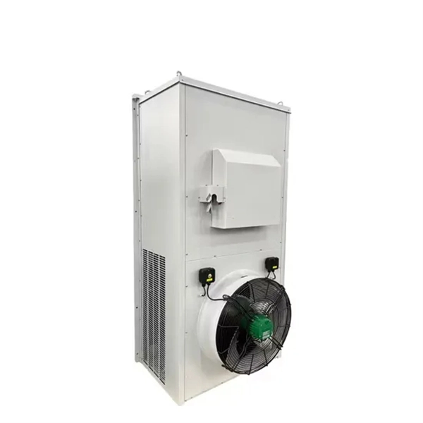
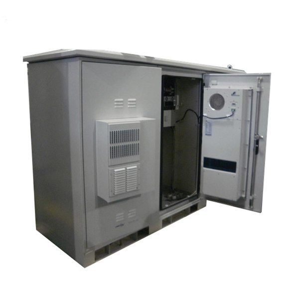
The primary purpose of a distribution box is to provide a safe and organized way to control electrical circuits. When an electrical fault occurs, such as an overload or short circuit, the protective
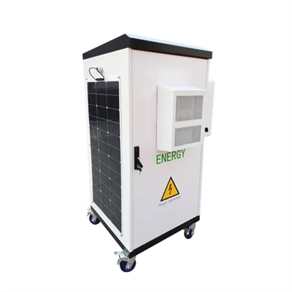
Each DISTRIBUTION BOX and controller must be grounded. On the US market, a 5.26 mm 2 (10 AWG) ground wire must be used, and in all other markets a 6 mm 2 must be used.
Contact us for competitive quotes on any of our power communication and smart grid products
Get a Quote