
Fieldbus Wiring Guide The purpose of this Fieldbus Wiring Guide is to provide information about the Fieldbus network so that its wiring system can be designed and installed for cost-effective and
There are two buses, one main bus and the other transfer bus also called an auxiliary bus. Each bay or equipment such as line, and transformer are
Find a detailed wiring diagram for Polaris busbar systems. Learn how to properly wire and connect your Polaris busbars for efficient and safe electrical distribution.
I''m upgrading a load of circuits from MCBs to RCBOs and as expected most of the distribution boards have singles that are randomly terminated on the bus bars so finding the
Read, understand and follow the guidelines and limitations herein for loading your console. Familiarize yourself with the warning symbols that appear throughout this manual. DANGER INDICATES A
Bus architecture plays a vital role in ensuring the smooth operation and coordination of various components in a computer system. In this article, we are
The end feed and/or above feed (not shown) units are used to make field wiring connections to the busway. Wiring connections are made to the copper blades by means of aluminum box style lugs or
6.4.2 Integrated cable management solutions as part of the aluminum housing (T5 series), capable of handling accessories such as the data channel cover, hinged wire way, data cable strap, and multi
Timing Bus: This bus line provides timing signals that synchronize the operation of various components within a circuit. These signals ensure that all components work together harmoniously, like the clock
For this drive, theoretically any motor phase wire wiring, there is a set of corresponding Hall wiring to make the motor operate normally, so you can first
Click on a sheet to start drawing a bus line. Double-click to finish drawing the line. -> [Parallel Wire]. -> [Auto Wiring]. Create wires from a component to the bus.
For further documentation, see: Introduction into TWI The two-wire interface consists of two signal lines named SDA (serial data) and SCL (serial clock) (plus a ground line, of course). All devices
The master initiates every communication on the bus down to the bit-level. This means that for every bit that is to be transmitted, regardless of direction, the master has to initiate the bit transmission. This is
Bus Wiring Harness Click HERE for Bus Battery Cables WIRING HARNESS, complete, Mid 1955-mid 1960 (chassis #569928) WIRING HARNESS, complete, Mid 1960 (chassis # 569929) - 1963 WIRING
Dcc bus wiring diagrams provide visual guidance on how to set up a digital command control bus for model railroads. See examples and learn how to wire
In the present planning manual we have compiled for you essential decision factors and technical information related to the use of SIVACON 8PS busbar trunking systems and their components.
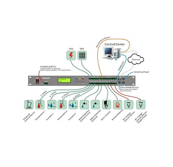
The document outlines the steps and procedures for bus wiring, which involves connecting panels in a structured manner to optimize cable usage and reduce
The wire harness assembly process begins with a good wire harness schematic design and includes simulation and analysis to maximize signal

Qwik flange is typically used only on Schneider Electric indoor equipment top exit/entry. Flanged end is typically used on all other Schneider Electric indoor/outdoor equipment, including third party
A comprehensive guide to the 1-Wire (Dallas/Maxim) bus protocol. Understand the critical timing for the master reset, slave presence-pulse, and the different bit slots for writing and reading data.
In der Rubrik 1-Wire Basics finden Sie Tipps und Tricks rund um den 1-Wire-Bus für Planung, Installation, Betrieb und Support. Wenn Sie neu in das 1-Wire-Bussystem einsteigen oder an
NEC® Article 215-8 requires that the high leg bus bar or conductor be permanently marked with a finish that is orange in color. This will help prevent electricians from connecting 120 volt single-phase loads
Learn about the CAN bus connection diagram, its components, and how data flows in a network. Understand the wiring, connectors, and key concepts behind the system.
By following these wiring guidelines, you can help ensure the reliability and performance of your Modbus network. Proper wiring practices will help minimize
21- The system phase squence should be checked in order to match the busway phases sequence before reconnecting all connections to transformers, switchboards, meters, etc.
A typical 1-Wire communication sequence. - MicroLAN Design Guide 2/32 vide timing margin for worse case conditions. A system clock is not required, as each 1-Wire part is self clocked by its own internal

This catalog includes information on features, construction, application, installation, electrical data, busbar configuration, wiring diagrams,
Contact us for competitive quotes on any of our power communication and smart grid products
Get a Quote