
This application note provides an in-depth analysis of the complete receiver optical sensitivity and the potential power penalties related to the accumulation of random noise and inter-symbol interference
Optical coherent receivers operate on the principle of mixing an incoming optical field (information channel) with a high power local oscillator (LO) signal prior to detection by the
Since most lightwave systems employ the binary intensity modulation, we focus on digital optical receivers. The figure below shows a block diagram of such a
How to change Speaker to Receiver (Optical) Sound Output on Samsung TV | Smart TV 2024 Tech & Design 453K subscribers Subscribe
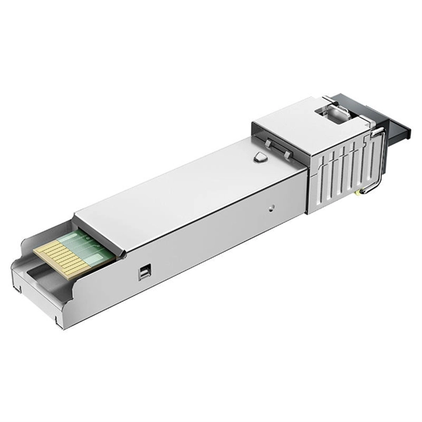
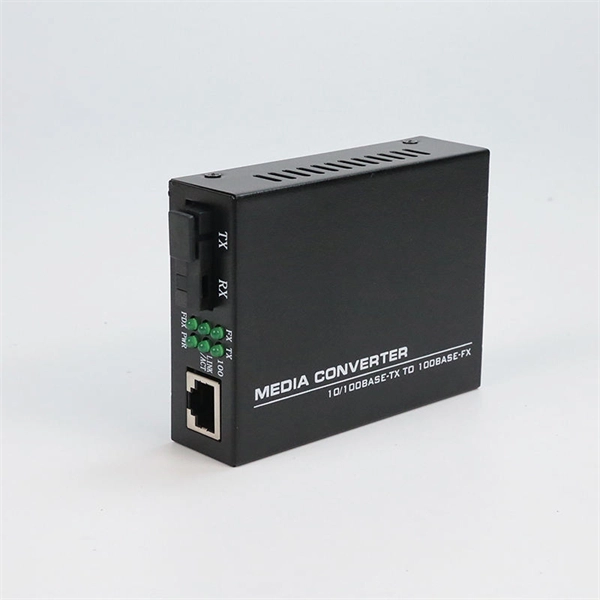
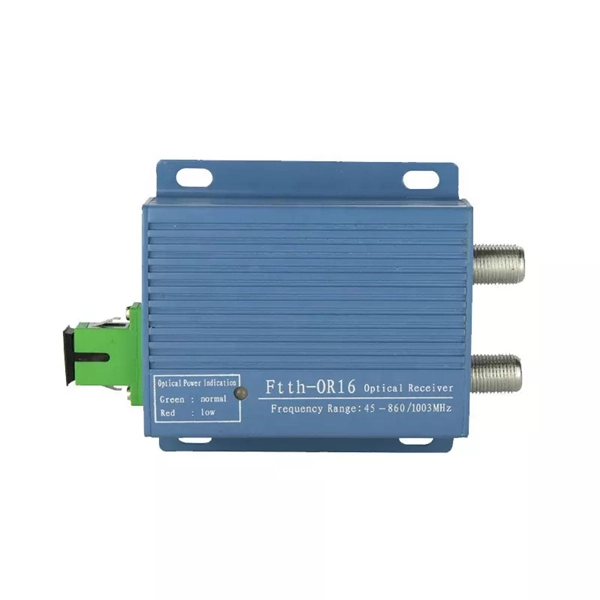
An ''Optical Receiver'' is a device that detects and converts the light received from a transmitter into an electrical signal. It consists of a photodetector and an amplifier, which work together to minimize
In this section, we discuss techniques to characterize optical receivers, with a focus on the wideband characterization of their frequency response.
TV Digital Audio Out Hookups This is a common hookup used when you have an over the Air Antenna or Smart TV with applications for movies or audio sources. The

n optical fiber to a distant receiver. The electrical signal is converted into the optical domain at the transmitter and is converted back into the orig nal electrical signal at the receiver. Fiber optic
Optical fiber is reliable, is very flexible, and is not sensitive to vibrations. Optical fiber is guaranteed for 25 years (compared to a guarantee of 10 years for satellite communications systems). Operating
The optical receiver, to be described in this chapter, consists of a photode tector and an associated amplifier along with necessary filtering. The function of the photodetector is to detect the incident light
Noise considerations are thus important in the design of optical receivers, Since the noise sources operating in the receiver generally set the lowest limit for the signal that can be processed.
The slope of the fiber trace shows the attenuation coefficient of the fiber and is calibrated in dB/km by the OTDR. In order to measure fiber attenuation, you need a fairly long length of fiber with no
Achieving accurate slope measurements with a laser level begins long before the laser is even turned on. Proper site preparation and meticulous equipment setup are critical steps that
Additionally, sound sent to the TV through an HDMI connection or other input also may not output through the optical port. In this case, the optical port from the source device (Blu-ray Disc Player,
Optimizing SNR is all about tipping the balance in favor of the signal you want, so noise doesn''t drown it out. That''s the key to reliable communication and measurement. You might be
Right-click in the list, select “Show Disabled Devices,” and enable the “Digital Output” or “Optical Output” device. Set this as your default device.
9.1 Introduction9.2.2 Detector/TIA wire bonding in optical subassemblies9.6 Characterization of clock and data recovery circuits9.7 Burst mode receivers9.7.3 Burst mode TIAs9.8 SummaryIn this chapter we consider issues related to the design of optical receivers. As signals travel in a fiber, they are attenuated and distorted, and it is the function of the receiver circuit at the other side of the fiber to generate a clean electrical signal from this weak, distorted optical signal. An optical receiver consists of an optical det...See more on link.springer Newport
An important property of optical receivers and detectors is the 3-dB bandwidth, which is defined by the frequency at which the output response drops to 50% of its value at DC or other low frequency
Therefore, this study analyzes site slope effect of a heliostat field at different latitudes, determines the most efficient site type at each latitude, and compares the site slope effect with layout
Recently concern has been expressed that the EVLA baseline design for the RF/IF system may have unacceptable gain variation across the wide bandwidths that the EVLA will require. The Project Book
The output optical signal from the loop is first split into two polarizations, each fed into an OFDM optical-to-RF down-converter that includes a balanced receiver and a local laser.
Having discussed the characteristics and operation of photodetectors in the previous chapter, the next step is to consider features of the optical receiver. An optical receiver consists of a
In this chapter we consider issues related to the design of optical receivers. As signals travel in a fiber, they are attenuated and distorted, and it is the function of the receiver circuit at the
In this section, we describe the implementation of the functionalities of the optical M-PSK transmitter and receiver using various photonic devices, i.e., a QM, a balanced receiver, a phase-diversity receiver
The sensitivity performance criterion for digital receivers is the error probability. The error probability is measured as the Bit Error Rate (BER), defined as the ratio of bits incorrectly identified to the total
In this chapter, we will introduce the basic concept of a high-speed receiver, the integrated circuit (IC) technique of the front-end. Subsequently, passive peaking techniques for a preamplifier are described.
Contact us for competitive quotes on any of our power communication and smart grid products
Get a Quote