
Download scientific diagram | Scheme of 10 kV overhead distribution network: T 35/10 kV -supply transformer; DB 10 kV -distribution busbar; F1 and F2 -10 kV
The utility model relates to a 35KV bus bar structure of transformer substation autotransformer lower voltage side delta connection.
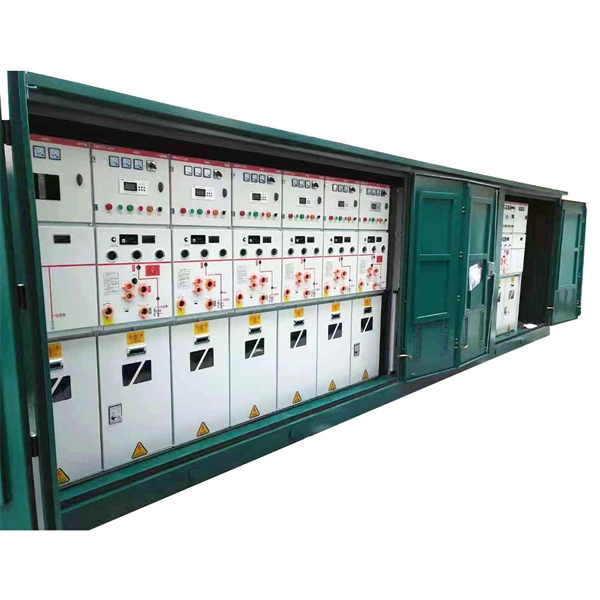
There are also busbars inside. The electric energy is passed from the outside of the incoming line cabinet to the circuit breaker through the busbar, and then the busbar is passed through the busbar.
Learn how transformer busbars improve current transfer, reliability, and efficiency. Explore copper vs aluminum, flatness, materials, and best design
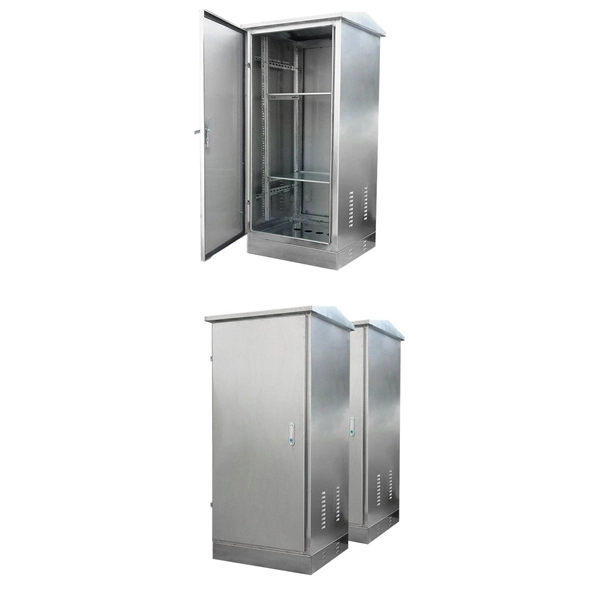
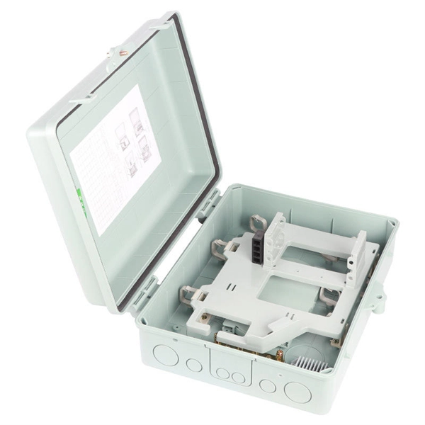
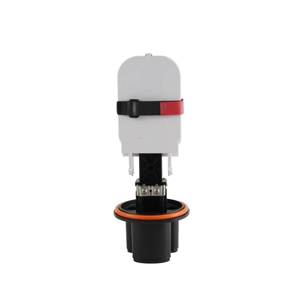
Suitable for the high voltage electrical apparatus of power plant, power transformer station at or under 35kV, such as cable branch box, combination transformer and incoming / outgoing line of GIS system.
132/33 KV EHV substation The project work assigned to us was to design a 132/33 KV EHV substation. We considered incoming power at 132 KV
Both busbars within a module, as well as the individual modules are to be fed from the same voltage source. If two or more different voltage sources (generator, transformer, constant voltage source,
In other words, Busbar is a junction where the incoming and outgoing feeders current meets i.e. it collects the power at single point. Busbars for Outdoors
The document then discusses the electrical main wiring designs for the substation, including selecting the main transformer capacity and type, designing the
Schematic of transformer bay MV/LV secondary substations present in the test subtransmission network: (left) single-busbar arrangement; and (right) double-busbar arrangement.
A technical diagram illustrating the common main wiring scheme (expanded external bridge connection) for 35~110kV substations, detailing the bridge structure layout, connections between transformers,
ABSTRACT Traditional bus bar current measurement techniques use closed loop current modules to accurately measure and control current. These modules usually require a large magnetic core that
Feeder Trunking Run Feeder trunking runs are used for the interconnection between switchboards or switchboard and transformer. Busbar

This paper made a design about a 35/10kV step-down substation according to the load of a town. The main technical focus is the primary electrical part design and a small part of the secondary design in
The joint edge of each busway conductor bar is beveled while the Pow-R-Bridge conductor bars have full rounded edges. This makes for a smooth and easy connection between the busway and Pow-R
Our busbar systems for electrical installations offer a particularly easy way of fitting distribution systems with electrotechnical components. The modular design saves space, while quick assembly contacts
This document is a schematic diagram for a 150 kV busbar protection panel arrangement and schematic for a project providing busbar protection systems
For a 200 MW photovoltaic power plant booster station, the installation of 35kV high-voltage switchgear and engineering construction program is a very critical part of the project, which is
At the end of this training module, users will be able to understand various connection configurations available for medium voltage transformers and associated accessories.
Wrapping skin tight PVC sleeve over busbars is not safe as it may bear cuts and cracks while sliding over the busbars. A perfect insulation as noted, is a pre-requisite for safe operation of sandwich

Connection diagram between the Distributor''s substation at the user site and the User''s passive system (CEI 0-16, Figure 7) specifications of the substation
7HQGHUHU¶V 6WDPS,QLWLDOV 3DJH RI 7(&+1,&$/63(&,),&$7,21 ±(/(&75,&$/:25.6 &217(176 $ 6&23( 2) :25. % 67$1''$5''6 & *(1(5$/ '' ''(7$,/('' 7(&+1,&$/ 63(&,),&$7,21 +7 3$1
Rigid busbar (OZh-CuprAl) is designed for electrical connections between high-voltage apparatuses of 3 phase AC, 50 Hz open (OSG) and closed (CSG) switchgears in the networks with nominal voltage of
KEY TO SYMBOLS NGC OWNED 400/132kV or 275/132kV TRANSFORMER TWO SECTION 132kV DOUBLE BUSBAR WITH BUS SECTION CIRCUIT BREAKER AND A BUS COUPLER IN ONE
The 400kV switchgear consists of four (4) 400kV Line/Transformer diameters plus one future diameter (Space only). Six (6) - single phase of 250/3MVA transformer (2units of complete transformer) shall
Figure 3 – Direct incomer diagram Where: Current transformer set Earth switch Voltage transformer (fused and withdrawable) A direct incomer
Panel for double busbar Fixed-mounted circuit-breaker switchgear NXPLUS is a factory-assembled, type-tested, metal-enclosed, SF6-insulated switchgear with metallic partitions 2) for single-busbar
Contact us for competitive quotes on any of our power communication and smart grid products
Get a Quote