
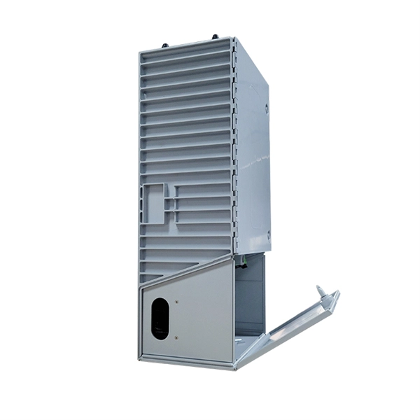
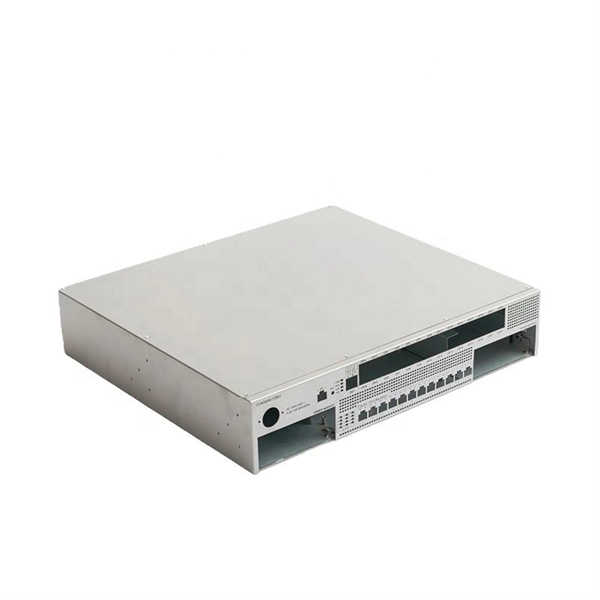
The 7807LR-2 and 7807LR-2-H Fiber Optic Receivers are used for receiving RF signals transported optically over fiber optic cable by a companion transmitter. They accept two optical inputs and
Download scientific diagram | Architecture of optical receiver and proposed limiting amplifier (LA) from publication: A 25 Gbps single‐end input limiting amplifier with
The LA adopts single-end input and differential output structure to reduce the complexity of optical receiver front-end and therefore decrease power consumption drastically. DCOC circuit
An ''Optical Receiver'' is a device that detects and converts the light received from a transmitter into an electrical signal. It consists of a photodetector and an amplifier, which work together to minimize
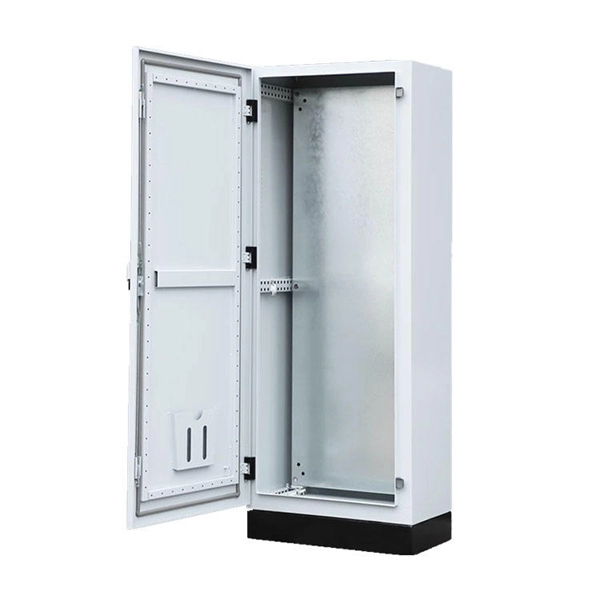
Safety instructions Installation of the receiver must be done according IEC60728-11 and national safety standards. The receiver is powered from low DC voltage, which is not dangerous to life.
To ensure safe operation of the receiver follow these instructions: Do not remove the cover of the power supply section, without disconnecting the unit from the mains supply. Do not plug the receiver into
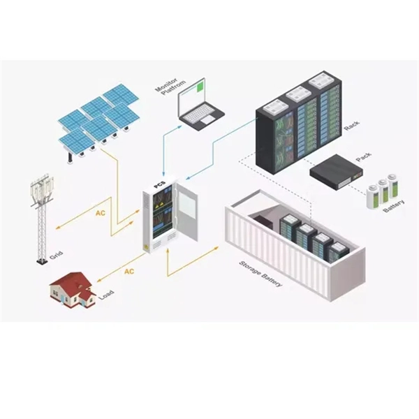
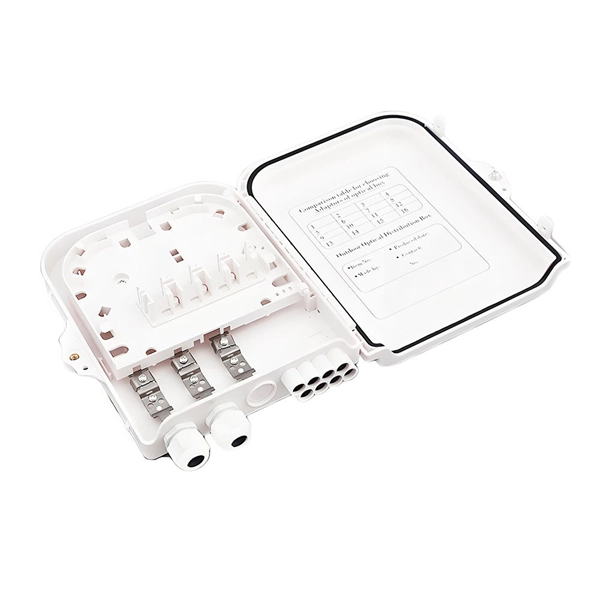
When a fiber optic network is in-stalled, a specific installation routine must be followed in order to have a quick and error-free operational net-work. It''s helping to keep this phrase in mind: “First time right.””
Abstract This document is intended to serve as a guide for architecting and deploying fiber optic networks in a customer environment. This installation planning guide describes some basic
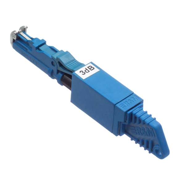
What Causes Poor Insertion Loss and Return Loss? Ideally speaking, if the fiber patch cable has no connections, then the minimum loss will be
Learn the difference between insertion loss and return loss in optical transceivers, their impact on performance, measurement methods, and LINK-PP
Safety instructions Installation of the receiver must be done according IEC60728-11 and national safety standards. The receiver is powered from mains 230 V~. This voltage is dangerous to life.
For example, assume: Power Budget in Optical Fiber calculations can be performed in two ways worst-case or statistically. With the worst-case approach, the values for launch power, receiver sensitivity,
Having discussed the characteristics and operation of photodetectors in the previous chapter, the next step is to consider features of the optical receiver. An optical receiver consists of a
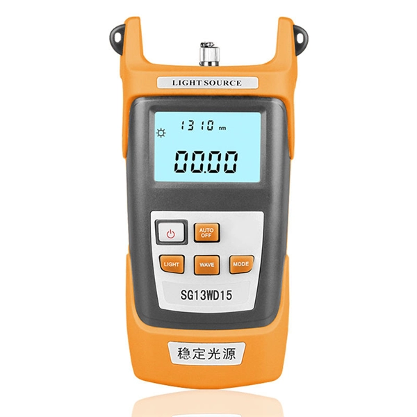
The MaxTester 945 Telco OLTS from EXFO is a tablet-inspired multifunctional optical loss test set that delivers insertion loss, optical return loss and fiber length
The input return loss of an optical receiver is the optical back reflection of the photodiode, measured at the fibre. The Optical Back Reflection is 10log10 (Prefl/Pin), in which Pin is the optical input power
The OMI-2 is a combined optical receiver and machine interface which is designed to be mounted within the machine''s working envelope . The OMI-2 operates using a modulated optical transmission mode
Fiber Optic Cable Installation and Handling Instructions Introduction Fiber optic cables can be easily damaged if they are improperly handled or installed. It is imperative that certain procedures be
The design of an optical receiver depends on the modulation format used by the transmitter. Since most lightwave systems employ the binary intensity
Before installation and operation carefully read these instructions. Observe the warnings given. These Fibre Transmiters are intended for indoor use only. Do not install the transmiters in damp, humid hot
Follow the manufactur-er''s instructions when installing the product. Never spill liquids on the LOR OTDR. The air intake and exhaust areas must be free from obstructions. Unrestricted air flow is
Dense arrays of optical detectors require very low-power, sensitive, and compact optical receiver circuits. Existing designs for the input receiver, such as TIA, require large power consumption to
instructions during installation. To ensure safe operation of the receivers follow these instructions: do not remove the cover of the power supply section of OD005P, without disconnecting the unit from the
The OTPN-3850 is designed to give optimum performance at a received CATV optical power (1550nm) of -4dBm although it will give good performance over the full rated optical input range of 0dBm to
Contact us for competitive quotes on any of our power communication and smart grid products
Get a Quote