
Features - Multimode & Single-Mode: Measures cabling attenuation across both multimode and single-mode fibers using combined power meter and quad-wavelength light source—great for diverse

To use a power meter for fiber optic testing, always clean connectors first with lint-free wipes or click-to-clean tools. Select the correct wavelength and set your reference. You measure
The performance of a fiber optic cable depends on its physical and optical characteristics. Below are the key technical parameters that define the capabilities of single-mode and multi-mode fibers commonly
Abstract: Devices and methods for optical measurements in point-to-point and point-to-multipoint networks, e.g. like PON networks with splitters are described in which reflected power from some
Optical power meter + light source — a two-instrument, end-to-end test used to measure absolute optical power and calculate insertion loss (dB) between two endpoints; this is the accepted method
Optical Power Meter (OPM) from AFL measures optical power in fiber optic networks, also measures insertion loss of MM or SM cables if used with Light Source.
Optical power meters typically use semiconductor detectors since they are sensitive to light in the wavelengths and power levels common to fiber optics. Most fiber
Check Optical Power Levels: Use a light meter to measure the optical power at the receiver. Compare the measured power to the receiver''s sensitivity
It is an essential tool for fiber optic technicians during the installation, testing, and maintenance of fiber networks. The device accurately measures optical signal power, typically in
IEC and TIA are developing new standards for MPO multi-fiber connector testing. FOA continues to provide practical, one-page standards for
Using an optical power meter and light source or OLTS (Optical Loss Test Set), Tier 1 Certification can be performed against industry standard limits

In order to predict the optical attenuation statistics from the visibility statistics for estimating the availability of the FSO system, the relationship between visibility and attenuation has to be known.
This setup lets OTDRs and fault locators analyze attenuation and connector loss at both ends of the fiber optic cable. Always stabilize your optical
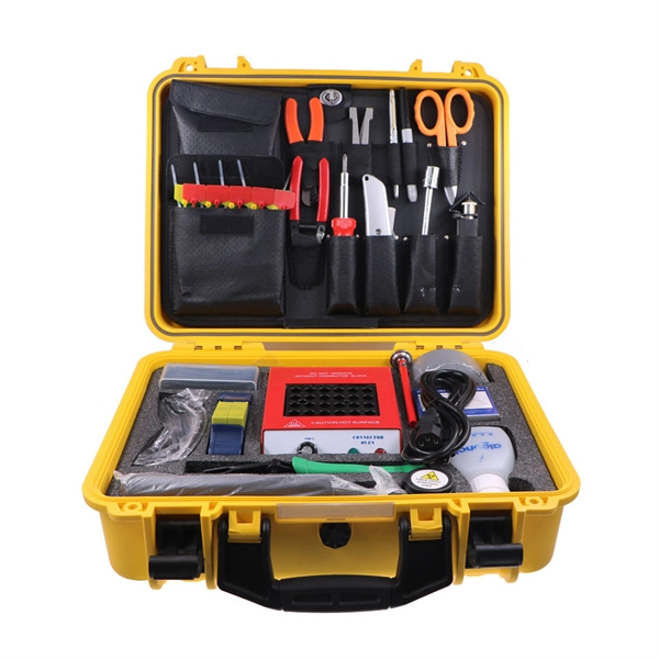
These universally applicable fiber optic instruments are easy to use and cost-effective, thus making it possible to equip all technicians performing fiber optic installation and maintenance.
Optical time-domain reflectometer An OTDR An optical time-domain reflectometer (OTDR) is an optoelectronic instrument used to characterize an optical fiber. It is the optical equivalent of an
Fixed access networks widely employ fiber-optical techniques due to the extremely wide bandwidth offered to subscribers. In the last decade, there
Optical power meters are indispensable instruments for testing and maintaining modern fiber optic communication and other
Insertion loss measures the total optical power lost as light passes through a connector, splice, or link segment. It is expressed in decibels (dB)—and unlike copper attenuation, which is
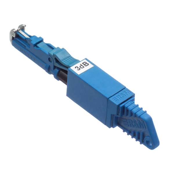
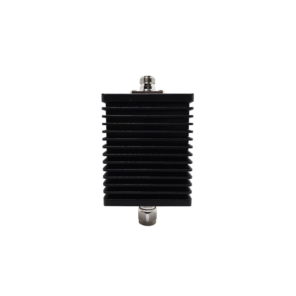
Fiber-optic attenuators adjust optical signal power levels, for example in fiber-optic links. The degree of attenuation may be fixed or variable.
Fiber loss, or attenuation, refers to the reduction in optical power as light travels through a fiber optic cable. While some loss is expected, excessive
🔵 Understanding OTDR (Optical Time Domain Reflectometer) in Fiber Optic Networks OTDR is one of the most essential testing tools used in modern fiber optic communication systems. It works by
Good for everyday testing, especially when installing or checking cables, the optical power meter only measures one wavelength at a time
Optics Lasers & Light Sources Optomechanics Fiber Optics Detection Devices Test, Measurement & Characterization Electro-Optics & Electronics Imaging &
The most basic fiber optic measurement is optical power from the end of a fiber. This measurement is the basis for loss measurements as well as the power from a source or presented at a receiver.
As attenuation levels increased, there was a corresponding decline in Q-factor, Eye Height, and optical power, coupled with a concurrent rise in the minimum BER.
Prior to system turn up, test the insertion loss of the cable plant with a source and power meter to ensure that it is within the loss budget. The idea of a loss budget
TRYLINSTY Optical Power Meter, Fiber Optic Cable Tester, Mini Fiber Light Meter w/9 Calibrated Wavelengths and FC/SC/ST Universal Interface Used for Optic Breakpoint Detection (-50+26dbm):
An optical power meter displays two key test parameters that allow fiber design specifications like insertion loss or low attenuation to be evaluated. The first is the wavelength setting in nanometers
Power losses in fibers can be measured and calculated in two ways by the optical power meter. The first method is to measure the light attenuation of the uncut
High-quality RF power watt meter, suitable for CB radio meters up to 5000W. Roughly starting from $9.25, order as few as 1 unit. Available in large volumes for bulk purchases.
Contact us for competitive quotes on any of our power communication and smart grid products
Get a Quote