
A capacitor bank is an arrangement of multiple capacitors connected in parallel or series that are used to store and release electrical energy. It is commonly used in electrical power systems to improve
The top of the junction box shall be mounted a maximum of 1''-0" below the capacitor bank frame. Leads to the capacitor switches shall be secured to the frame of the bank with wire ties. The junction
What is a capacitor bank and why is it used? Short Answer: A capacitor bank is a group of capacitors connected together to improve the
With this being said, the wiring diagrams of a capacitor bank are essential for understanding how it works and for ensuring that it is wired
The final programming step is to verify the working of the capacitor bank. This is done by activating the controller in manual control mode and cycling through all the available steps.

This article unfolds with a detailed exploration of the double-star configuration adopted for the capacitor bank within the substation, coupled with the intricacies of the selected protection
This paper reviews principles of shunt capacitor bank design for substation installation and basic protection techniques. The protection of shunt capacitor bank includes: a) protection against internal
Learn optimal capacitor bank placement and wiring: location at load vs centralized, and star/delta (grounded/ungrounded) connection choices.

Learn how to design a capacitor bank correctly — covering parallel and series configurations, DC link sizing, PFC resonance risks, current sharing, anti
Introduction The protection of shunt capacitor banks requires understanding the basics of capacitor bank design and capacitor unit connections. Shunt
This article unfolds with a detailed exploration of the double-star configuration adopted for the capacitor bank within the substation, coupled with
Generally, an individual capacitor is used to store electrical energy. So once capacitors are increased within a bank then it will increase the energy capacity
Understanding the basics of capacitor banks, how they are installed, and the importance of wiring diagrams can greatly improve the reliability and efficiency of your power systems. Taking
Capacitor banks are groups of capacitors connected together in power systems to supply reactive power locally. Their main function is to compensate for the lagging reactive power caused by

1. Description REV615 is a dedicated capacitor bank relay designed for the protection, control, measurement and supervision of capacitor banks used for compensation of reactive power in utility
Key learnings: Capacitor Bank Definition: A capacitor bank is a collection of multiple capacitors used to store electrical energy and enhance the
Capacitor banks play a vital role in modern electrical systems by enhancing power factor correction, improving energy efficiency, and ensuring voltage stability.
A 3 phase capacitor bank wiring diagram provides all the necessary information to ensure safe and efficient installation of the electrical components. The basic
In-Depth Guide to Capacitor Banks Let''s discuss capacitor banks, but this time, not the basics. Let''s study the double-star capacitor bank configuration
Shunt capacitor banks are protected against faults that are due to imposed external or internal conditions. Internal faults are caused by failures of capacitor elements composing the capacitor units,
Shunt capacitor unit features Protection of shunt capacitor units calls for knowledge of the advantages and restrictions of the capacitor unit and related electrical devices that include: individual capacitor
To create a capacitor bank wiring diagram, you will need to understand the different components and their interconnections. The first step in creating a capacitor
Learn how to wire a capacitor effectively with this detailed guide. Discover step-by-step instructions, expert tips, and common FAQs answered.
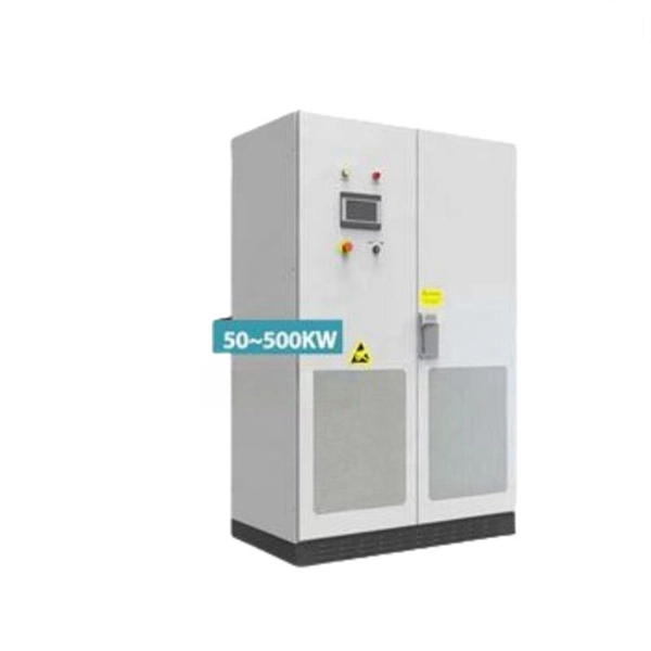
Capacitor bank is used for reactive power compensation and power factor correction in the electrical substation.
If a 120V voltage source for the controller is not available from the circuit the capacitor bank is being installed on, refer to DCS 16 15 05 01 for 1kVA transformer installation.
Principles of Shunt Capacitor Bank Application and Protection Satish Samineni, Casper Labuschagne, and Jeff Pope, Schweitzer Engineering Laboratories, Inc.
Relay Fail, DC Fail, and AC Fail. Suggested Study – Restricted earth fault relay application within a 400kV shunt capacitor bank design Restricted earth fault relay application within
⚡ Capacitor Bank Connection & PPM Procedure Removal and Cleaning Process – Electrical Maintenance Guide I''m explaining the connection of a capacitor bank, along with the Preventive
The KPC capacitor bank is wired in parallel with the load. Refer to NEC wiring practices for appropriate wire sizes for your application. Power Wiring: Only use 75°C copper conductors unless the wire
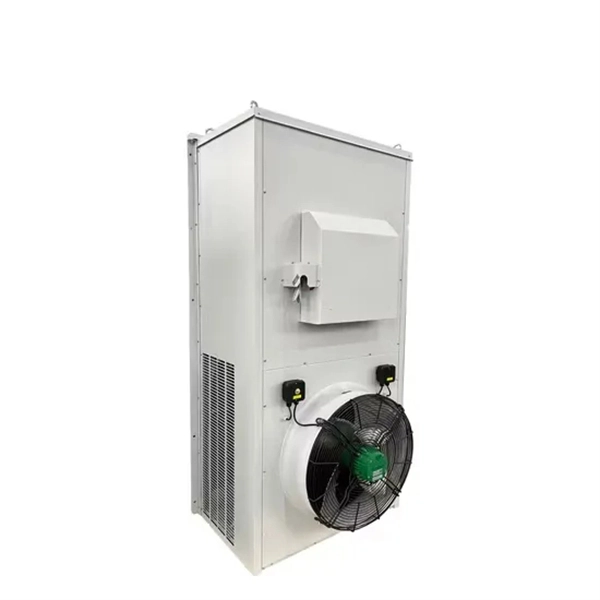
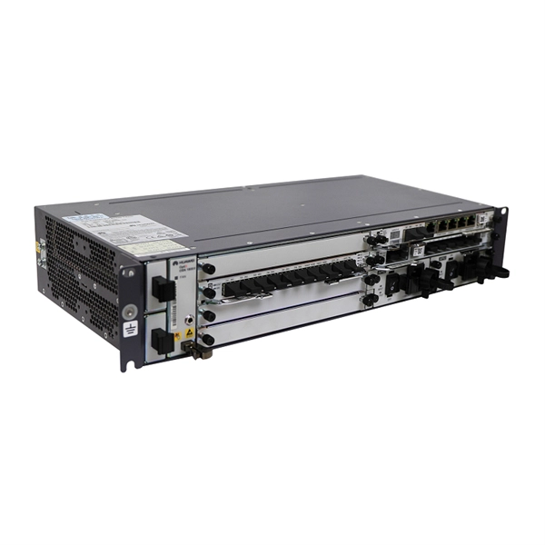
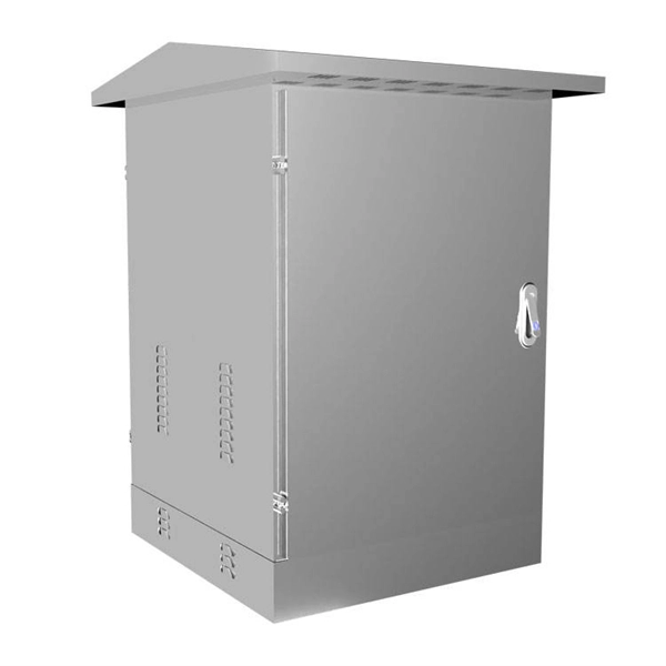
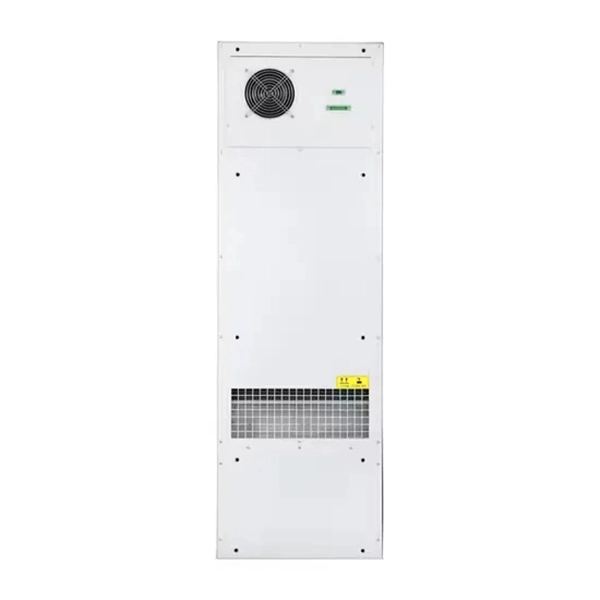
Contact us for competitive quotes on any of our power communication and smart grid products
Get a Quote