
The attenuation coefficient of the fiber is measured by the manufacturer at 1310 nm, but your test source may have a wavelength slightly different. If your source
Pulse broadening due to chromatic dispersion and the variation of fiber attenuation with wavelength can become issues with DWDM. All these factors need testing on long distance networks to ensure
Learn how to use an OTDR device to test and analyze fiber attenuation in the field. Find out the benefits, challenges, and tips of OTDR testing.
Test for return loss, polarization mode dispersion, and spectral attenuation if required by your project. Use specialized
Stay compliant in 2025 with updated fiber testing standards for IEC and TIA. Learn key procedures, documentation tips, and legal requirements for
Tier 1 testing is the minimum level of testing that is required. This level of testing consists of link attenuation testing, link length, and a polarity check. The fibre optic link attenuation is tested using an
Attenuation and Dispersion in Fiber-Optic Cable Correct functioning of an optical data link depends on modulated light reaching the receiver with enough power to be demodulated correctly.
Discover the causes and effects of attenuation in fiber optic cables. Learn about scattering, absorption, bending losses, and how to limit signal
required. This level of testing consists of link attenuation testing, link length, and a pola ity check. The fiber optic link attenuation is tested using an optical loss test set (OLTS) or a light source and power
Six basic fiber-optic cable tests A half-dozen simple but rigorous tests, performed with an optical time-domain reflectometer and an optical power meter, characterize the optical...
Fiber attenuation measurements Fiber attenuation measurement techniques have been developed in order to determine the total fiber attenuation of the relative contributions to this total from both
ATTENUATION.—The fiber optic test method for measuring the attenuation of an installed optical fiber using an OTDR is EIA/TIA-455-61. The accuracy of this test method depends on the user entering
Fiber Characterization Testing For Long Haul, High Speed Fiber Optic Networks: Chromatic Dispersion, Polarization Mode Dispersion and Spectral Attenuation
Prior to installation, fiber inspections are performed to ensure that the fiber cables received from the manufacturer conform to the required specifications (length, attenuation, etc.) and have not been
Learn about insertion loss failure, causes,measurement, troubleshooting and testing . Insertion Loss Vs Attenuation, attenuation is now replaced with term “insertion loss”.
In fiber network installation, accurate measurement and calculation of attenuation in optical fiber is a very important step to verify network integrity and ensure network performance.
This document describes how to calculate the maximum attenuation for an optical fiber. You can apply this methodology to all types of optical fibers
2. Why Test? Imagine your end user calls to report his recently installed cabling system is not functioning. So, you drop everything and investigate. He''s right – it is not working. However, because
Once all your fiber connections are made, there are two testing methods that can be used to evaluate the performance of the installed fiber optic system: OLTS and OTDR. Learn about their
Learn about fibre optic cabling loss limits & how to calculate them. Gain insights from experts on acceptable loss for cabling projects & explore the
Technical guide to testing fiber cable quality, covering visual inspection, optical loss testing, OTDR analysis, and standards for FTTH and
To be able to judge whether a fiber optic cable plant is good, one does a insertion loss test with a light source and power meter and compares that to an estimate
Ultra Low Loss Fiber Performance Calculator Calculate link or channel loss and determine the supported applications and max lengths for the configuration. The configuration and results can be exported as
This section describes different channel impairments, including fiber attenuation, insertion losses, chromatic dispersion, PMD, and fiber nonlinearities. The frequency chirp effect was described
Attenuation causes light to weaken as it travels through fiber optic cables. Learn why it happens, what affects it, and how engineers measure and manage it.
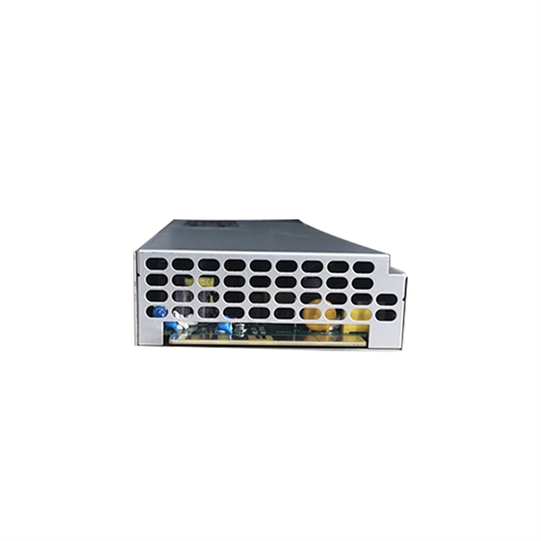
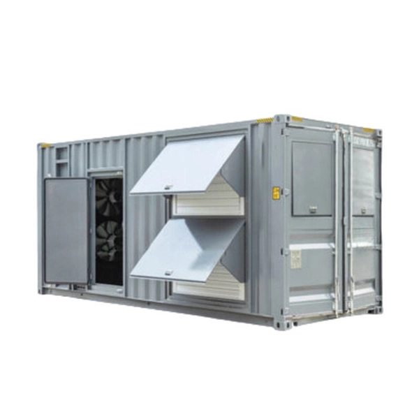
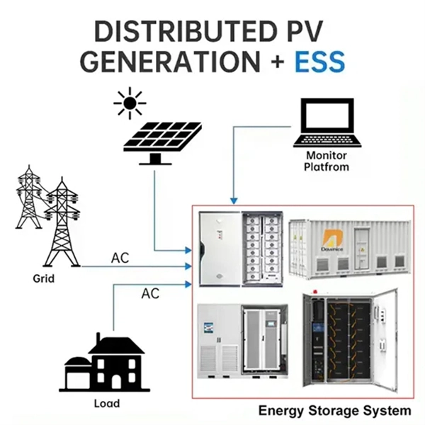
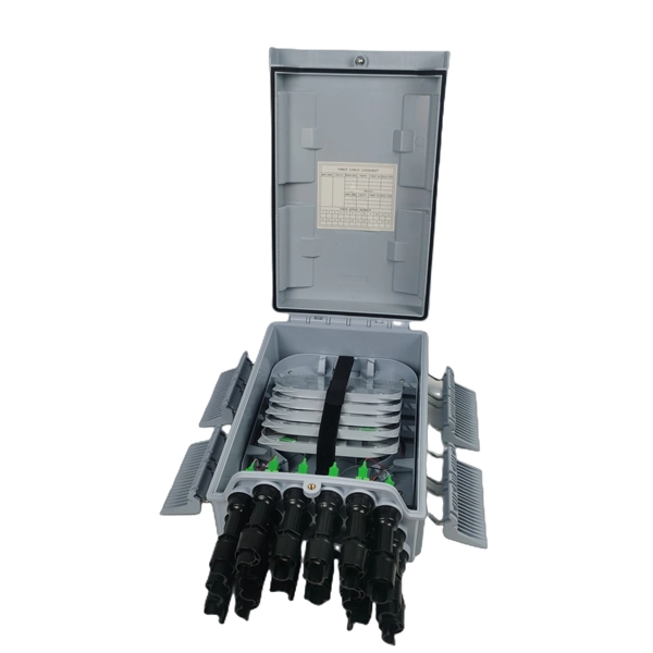
Contact us for competitive quotes on any of our power communication and smart grid products
Get a Quote