
Explore copper busbar insulation methods, including heat-shrink tubing and epoxy coating. Learn about process techniques, advantages, and
Tubular Busbars: Supported by column insulators (usually ceramic), these offer high mechanical strength and superior corona resistance. Stranded-Wire
Use of High-Force Press-Fit for Busbar Interconnects Solderfree interconnects, such as press-fit technology, offer a straightforward solution to these issues because they provide excellent
Whether for new installations or upgrades, RTEK''s high temperature busbars are modular, easy to install, and compliant with international electrical and safety standards, making them the ideal
Avoid certification failures and costly redesigns. This guide compares IEC, ANSI, and GB busbar standards with real
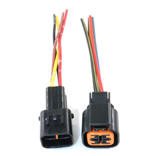
Power connectors inside of server racks may undergo temperature-related failures, causing service disruption. Outfitting power connectors and busbars with
Ceramic Composite Tape Busbars: These battery busbars combine heat-resistant ceramic tape with conductors to meet EV system demands for insulation, heat
Taking the uncertainty of contact resistance into account, this paper presents an indirect approach to monitor the conductor temperature for the fully insulated busbar prefabricated joint using the busbar
POWER BUSBAR SOLUTION TE Connectivity''s busbar solutions are typically made from aluminum or copper with electrical distribution applications in mind, with the ability to transmit high current power
Connections of the busbars in switchgears are studied from the point of view of the electrical contact resistance and of the temperature (tests an d
Battery busbars combine heat-resistant copper conductors with ceramic-based insulation to ensure dielectric strength, high-temperature endurance, and mechanical durability. Automated winding
This paper presents a mathematical model for analyzing the thermal behavior of copper busbars in high current power supply systems, focusing on
Busbar undersizing for temperature rise causes conductor overheating that degrades insulation, increases contact resistance at joints, and accelerates material aging. When busbars
Thermal shock test, thermal shock resistance Automotive components are subjected to severe temperature cycling and thermal shock tests. Busbars are made of several materials (copper,
In this paper, a mathematical model related to the temperature rise distribution of a busbar from a high current power supply, is described. The thermal model allows for computation of the temperature rise
This layer, typically 0.5mm thick, provides strong electrical insulation, corrosion resistance, and excellent heat dissipation. With high temperature and voltage resistance, it is ideal for special-shaped rigid
Epoxy powder coatings provide a uniform, durable insulating layer over busbars. This method offers excellent dielectric properties and resistance
Figure 10 Flexible Bus Bar Installation The flexible bus bar system overcome these common problems faced by cable and rigid bus bar solution in high current density applications:
Conductor selection Busbars are ideal for the high-power applications that are commonplace in EVs. OEMs first started using busbars in EV battery packs as interconnects for battery modules. To
Regarding fill materials, Interplex busbar design teams have found good results with high-temperature, glass-filled plastic molding solutions, such as Polyphenylene Sulfide (PPS), PPA, or PBT, depending
Connections of the busbars in switchgears are studied from the point of view of the electrical contact resistance and of the temperature (tests and thermal simulations), with some parameters such
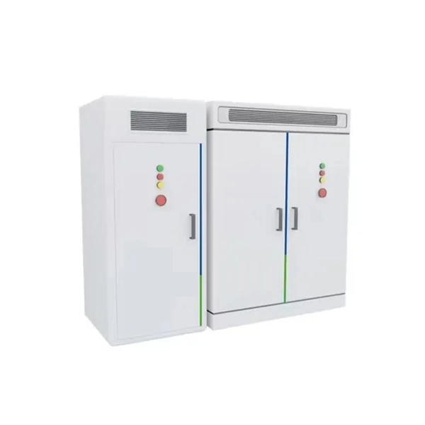
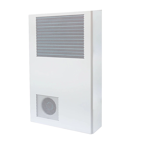
Thermosetting plastics like epoxy resin offer excellent heat resistance up to 150°C, while aluminum or galvanized steel casings provide both mechanical protection and heat dissipation.
A leading provider of bus bar solutions, Methode Power Solutions Group delivers products that meet RoHS and REACH standards, as well as assemblies that are
When the contact resistance in the busbar joint area increases, the heat pipe structure decreases the maximum temperature by 1.07 K to 7.16 K. These research findings indicate that the

Conclusion Thermal runaway in electrical busbars is a serious concern that can lead to system failures, fires, or even explosions. However, by implementing the
a high current power supply, is described. The thermal model allows for computation of the temperature rise in the case of electric current variation, cross‐section and length variation of the busbar, and
Contact us for competitive quotes on any of our power communication and smart grid products
Get a Quote