
To confirm a cold solder joint, you can use a multimeter to test continuity. A cold solder joint forms when the solder does not properly bond the component lead to the pad—typically due to inadequate heat, oxidation, or poor technique. Generally, its appearance is smooth and bright. This guide explains what a cold solder joint is, what it looks like, why it happens, and how to reliably identify, fix, and prevent it. Whether you're troubleshooting a failed board or optimizing an SMT production line, this article gives you a practical, engineering-level reference for eliminating. Ultrasonic Pulse Velocity (UPV) is an effective non-destructive testing (NDT) method for quality control of concrete materials, and evaluating concrete integrity on or around the cold joint.
This TIDA-00427 design guide summarizes the results of 100G CAUI-4 testing using the DS280BR810 low-power, 28-Gpbs, 8-channel linear repeater from Texas Instruments (TI). By building test scenarios and simulating the customer's usage environment, we test whether the module's performance meets the customer's requirements. Test Data Confirm the brand, quantity and placement of the switches to be tested. Test DataThe test topology involves connecting a Juniper QFX5120-48Y-8C switch using a QSFP28-SFP28-CVR module and a 25Gbps SFP-25GSR-85 module. Prepare control cables, test software, and. Refer to the Two-Port 40- and 100-GbE QSFP28 Signal Conditioner Reference Design (TIDUBG6) for more details on the test. Testing these modules ensures performance, compatibility, and long-term reliability in bandwidth-intensive environments like. FINISAR has model QSFP28-100G-LR4 optical module products, which can support 100G Ethernet transmission 10KM in single-mode fiber, Moduletek Laboratory has tested the sample of this product, which is convenient for you to know more about the performance index of this product and the effect of using.
[PDF Version]
Power meter testing will be conducted at both wavelengths (if under 64 km) and only at 1550nm for spans greater than 64 km. The term usually refers to a device used for measuring the average power in fiber optic systems. Other general purpose light power measuring devices are usually called radiometers, photometers, laser power. While optical power meters are the primary power measurement instrument, optical loss test sets (OLTSs) and optical time domain reflectometers (OTDRs) also measure power in testing loss. Consistent procedures ensure accuracy. Verify light travels from. OWL manufactures a complete line of fiber optic test equipment for a wide range of applications, including telco, WAN, MAN, LAN, SAN, CATV, IT, manufacturing, and laboratory. OWL's complete line of fiber optic testers have capabilities ranging from simple optical power and optical loss measurement. An optical power meter (OPM) measures the power levels of light signals in devices that transmit data or power using light.
[PDF Version]
Most OTDR devices allow you to save test results directly to the device's internal memory, a USB drive, or a cloud storage service. The method depends on the OTDR model you're using, but it is generally straightforward. An Optical Loss Test Set (OLTS) measures insertion and return loss across fiber links. They support singlemode and multimode. When working with an Optical Time Domain Reflectometer (OTDR), one of the most important things you can do is appropriately save, export, and interpret your test results. This is the software used to change the raw test files from the Versiv into a readable report, whether that's a. You are asked to edit its. KITSTM software is a flexible solution for real time data acquisition, analysis and reporting of fiber optic attenuation, power & optical return loss (ORL). KITSTM dramatically improves testing productivity, lowers skill level, minimises errors and enhances report customizing capability. But which one is right for you? Self-hosted.
[PDF Version]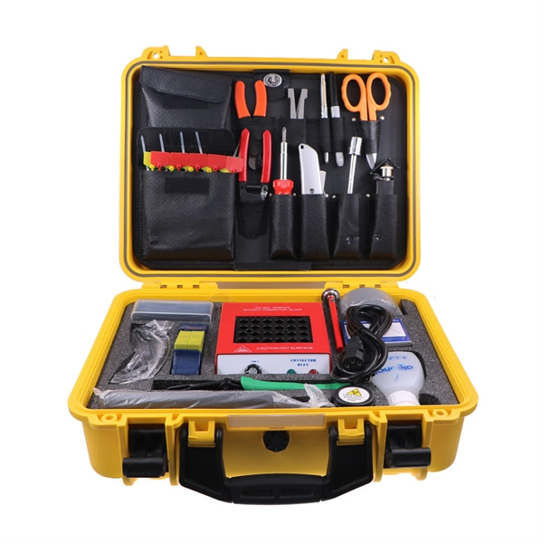
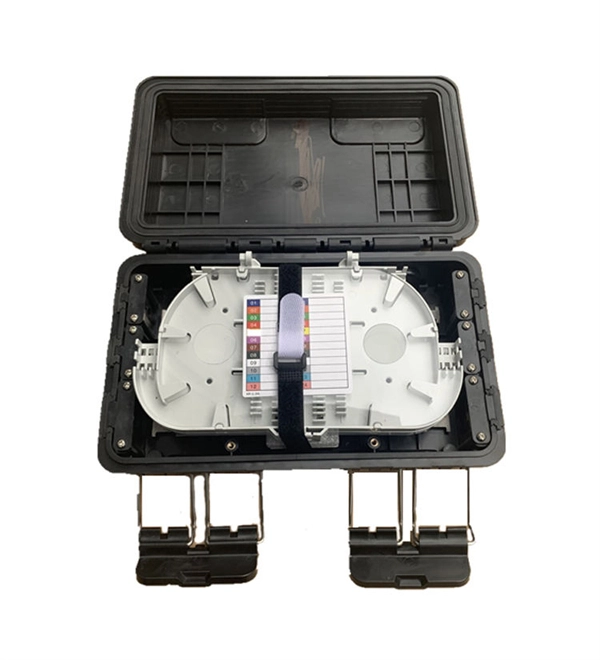
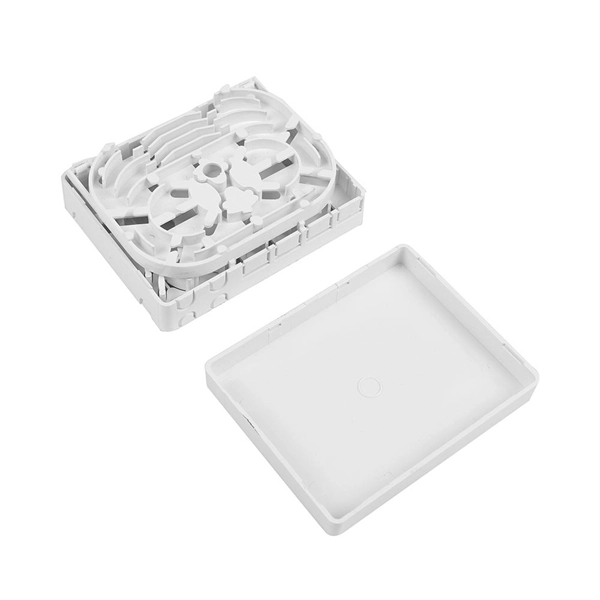
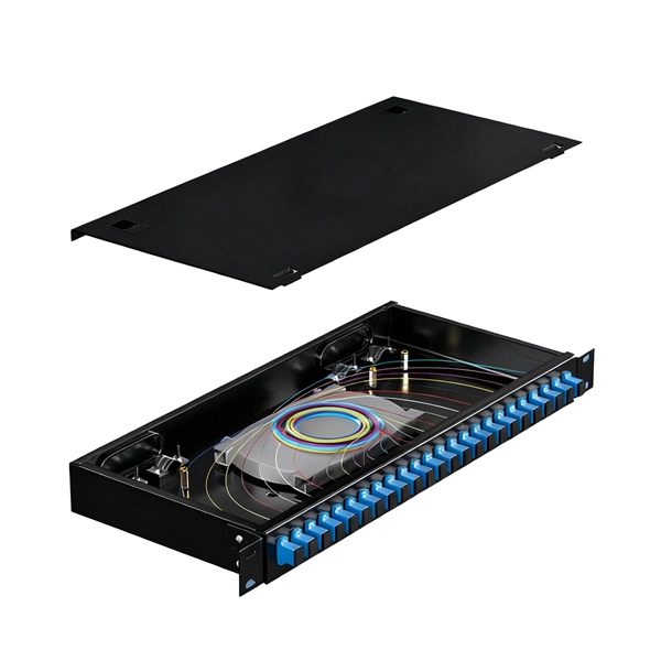
Fiber Termination Box, also known as FTB, typically consists of two main parts: the outer shell body and the adapter tray that protects the fiber connector points. It is a crucial component in fiber optic networks, primarily used for terminating, connecting, and managing fiber. In every fiber build, there's a quiet place where the glass path meets the real world: the fiber optic terminal box. It's where delicate strands are protected, splices are routed, connectors are exposed for patching, and future changes are made painless—or painful. Choosing the right fiber optic. First and foremost, a fiber optic terminal box serves as a robust protective shield for fiber optic cables and their delicate connections. Fiber optic cables, composed of ultra thin glass or plastic fibers that transmit data as light signals, are extremely fragile.
The Fiber Test Box offers you the optimal solution to use fiber optics for simulations, tests and demo applications in an efficient and space-saving way. Fiber type, length and connector type can be customized via our. Customized Fiber Lab solutions provide the most efficient, hassle-free way to use and manage spools of optical fiber for accurately simulating field network spans and links or deploying optical time delays. Offering precision lengths of all fiber types available from leading global manufacturers. Whether they are called a launch box, pulse suppressor, or launch cable they all do the same thing. These fibers are most commonly made of glass and are very thin, typically less than a tenth of the width of a human hair.
H3C QSFP-100G-ER4-SM1310 compatible optical transceiver module is designed with duplex LC connectors, reaching a link up to 40km with FEC; 30km without FEC over single-mode fiber (OS2). Transceivers are mainly used for optical-to-electrical and electrical-to-optical conversions and provide the following functions: optical power control, modulation transmission, signal probe, IV conversion, and limiting amplifier and decision regeneration. In addition, transceivers provide some. This H3C SFP-GE-SX-MM850-A optics is a high performance and cost-effective small form factor pluggable transceiver. It is suitable for 1000BASE-SX Gigabit Ethernet and 1G Fibre Channel application. The product is supports up to 550m link lengths over. All contents in this document, including statements, information, and recommendations, are believed to be accurate, but they are presented without warran y of any kind, express or implied. H3C shall not be liable for technical or editorial er ronmental protection. Original compatible & refurbished H3C transceivers. SFP+ QSFP QSFP28 DAC AOC - H3C 10GB-SR 10GB-LR 25GB 100GB QSFP56-H3C Optical Transceivers.
[PDF Version]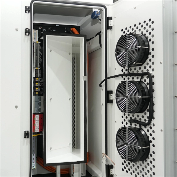
The system in this example contains the following elements: 1. 2 Pseudo-random Bit Stream (PRBS) block 2. 2 NRZ Pulse Generator (NRZ) 3. 1 CW Laser (CWL) 4. 3 1x2 Fork (FORK) 5. 2 Electrical Not Gate (N.
At the heart of every optical transceiver lie three essential components, often called the “Three Pillars” of optical communication: Laser — generates light. Modulator — encodes data onto the light. The following will focus on optical components and. Optical modules are devices used to connect network devices, transmit and receive data between network devices, and can be used to convert optical and electrical signals. Optical modules typically have an electrical interface on the side that connects to the inside of the system and an optical interface on the side that connects to the outside.
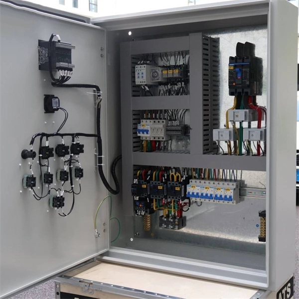
Contact us for competitive quotes on any of our power communication and smart grid products
Get a Quote