
Instead of a metallic coating, a dichroic optical coating may be used. Depending on its characteristics (thin-film interference), the ratio of reflection to transmission will vary as a function of the wavelength of the incident light.OverviewA beam splitter or beamsplitter is an that splits a beam of into a transmitted and a reflected beam. It is a crucial part of many optical experimental and measurement systems, such as In its most common form, a cube, a beam splitter is made from two triangular glass which are glued together at their base using polyester,, or urethane-based adhesives. (Before these synthetic,. Beam splitters are sometimes used to recombine beams of light, as in a. In this case there are two incoming beams, and potentially two outgoing beams. But the amplitudes.
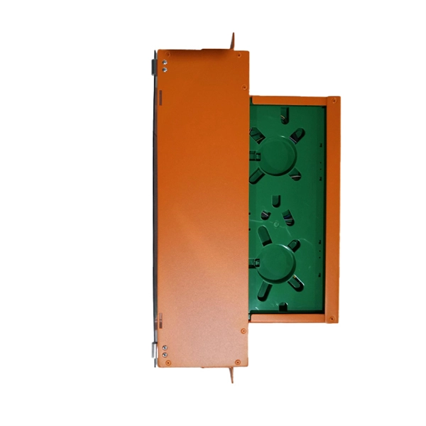
A GPON splitter is a passive optical device that takes a single fiber input and splits it into multiple outputs, typically in ratios like 1:2, 1:4, 1:8, 1:16, 1:32, and 1:64. The splitting process introduces signal attenuation, making placement strategy critical for. Gigabit Passive Optical Networks (GPON) have revolutionized fiber-optic broadband by offering high-speed connectivity to multiple users over a single fiber. A key component enabling this efficiency is the optical splitter, which divides the optical signal to serve multiple endpoints. There are no specific requirements for this document. In this guide, you'll learn how fiber splitters function in PON networks, the difference between PLC and FBT types, and how to choose the best. A fiber-optic splitter, also known as a beam splitter, is based on a quartz substrate of an integrated waveguide optical power distribution device, similar to a coaxial cable transmission system. Conversely, it can also combine multiple signals into one.
[PDF Version]
A beam splitter or beamsplitter is an that splits a beam of into a transmitted and a reflected beam. It is a crucial part of many optical experimental and measurement systems, such as, also finding widespread application in.
QSFP-DD is a new module and cage/connector system similar to current QSFP, but with an additional row of contacts providing for an eight lane electrical interface. It is being developed by the QSFP-DD MSA as a key part of the industry's effort to enable high-speed solutions. The Cisco ® QSFP-DD Open Line System (QSFP-DD OLS) is a pluggable optical amplifier module that, together with the channel breakout options (described later), provides a simple yet powerful open. The QSFP-DD OLS is a pluggable open line system solution that can be directly hosted on a Cisco router. 8mm pitch and a dual-mating interface. QSFP-DD extends the use. Supporting the continuing growth in the bandwidth demand and datacenter traffic driven by networking and AI/ML requirements, the QSFP-DD (Double Density) Interconnect System delivers 8 lanes with up to 28 Gbps NRZ or 56 Gbps-PAM4 (up to 400 Gbps aggregate) in a compact footprint that is backward. Get best-in-class optics from legacy GBICs to cutting edge 1. Harness the power of Proline's quality by design. Explore our cutting-edge coding & testing lab.
[PDF Version]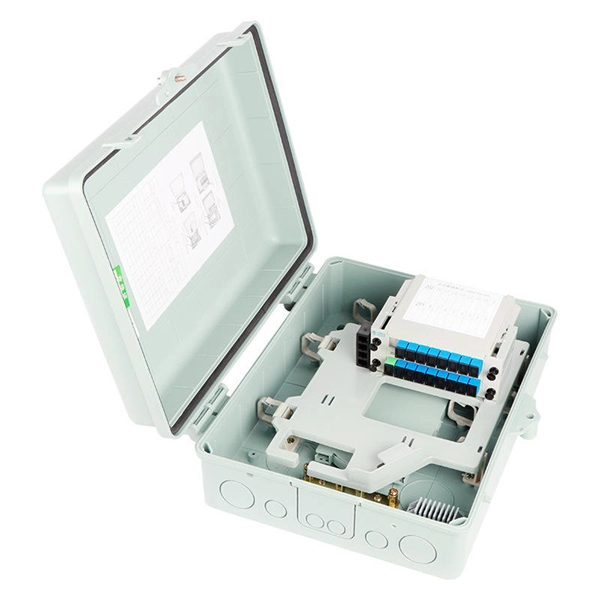
Optical transceiver interoperability refers to the ability of transceiver modules from different manufacturers to function correctly with a range of networking equipment—switches, routers, servers, and optical transport gear—without compatibility issues. This guide dives deep into the core aspects of optical transceiver compatibility, common. When it comes to the connection between two fiber optic transceivers, the following four factors should be taken into considerations: wavelength, speed, fiber type, and the connection to switches. In a fiber link, the data is transmitted from one end to another, and fiber transceivers are. Several years ago, hyperscale network operators saw an opportunity for coherent Dense Wavelength Division Multiplexing (DWDM) transport optics to plug directly into routers for 400 Gbps Data Center Interconnections (DCIs) with reaches up to 120km. This point-to-point, IP-over-DWDM architecture. MSA (Multi-Source Agreement) standards define the mechanical, electrical, and management interfaces of optical transceivers, enabling multi-vendor interoperability, supply chain flexibility, and large-scale network deployment.
[PDF Version]
To test fibre splicer quality, begin by inspecting cleave angles and fibre cleanliness. Next, confirm arc calibration and alignment using the splicer's splice loss estimation. Follow up with OTDR or ILM testing to validate results. In this guide, we'll explore what splicing of fiber entails, why it's important, and dive into the key methods and tools. Fusion splicing is the process of fusing or welding two fibers together usually by an electric arc. Fusion splicing is the most widely used method of splicing as it provides for the lowest loss and least reflectance, as well as providing the strongest and most reliable joint between two fibers. fCONSTRUCTION QUALITY REQUIREMENTS FOR FTTP & SSP Work Orders This document provides Construction Technicians, Construction Managers, FTTP/SSP Vendors, and Inspectors with the essential information to ensure a quality build and to successfully pass an Outside Plant Inspection. This testing. This Applications Engineering Note (AEN 135) explains and recommends standard measurement methods for characterizing optical fiber system performance.
[PDF Version]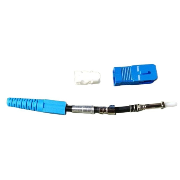
Fiber Type and Count: Single-mode fiber typically costs $0. This guide compares multimode cable prices across OM1–OM5 and explains what really moves the number: fiber grade, fiber count, jacket rating, and whether assemblies are factory-terminated. Thorlabs' line of high-quality fiber optical bundles consists of either 7 or 19 high-grade optical fibers in a round configuration combined in an SMA905 connector. Versions are available with either low-OH or high-OH fibers. Custom-built cables or niche specifications can lead to higher prices. For planning, consider a project-wide range of $1,000 to $30,000+ for several hundred to several thousand feet, with per-foot costs.
A fiber cable, also known as an optical fiber cable, is a type of cable consisting of one or more optical fibers that are used to transmit digital...
Single-mode fiber cables have a smaller core diameter and allow only one mode of light to propagate through the fiber, resulting in less signal att...
A fiber bundle is a collection of optical fibers that are bundled together to form a larger cable. Fiber bundles are often used in medical imaging...
The cladding on a fiber cable is a layer of material surrounding the core of the cable, which helps to keep the light signals confined within the c...
The numerical aperture of a fiber cable is a measure of the light-gathering ability of the cable. It is determined by the refractive index of the c...
Fiber optic attenuation is the loss of signal strength as light travels through a fiber optic cable. It is measured in decibels (dB) and can be cau...
A fiber optic patch cable is a short length of fiber cable with connectors on both ends, used to connect optical devices such as routers, switches,...
Dispersion is the broadening of a light pulse as it travels through a fiber cable, caused by differences in the speed at which different wavelength...
Contact us for competitive quotes on any of our power communication and smart grid products
Get a Quote