
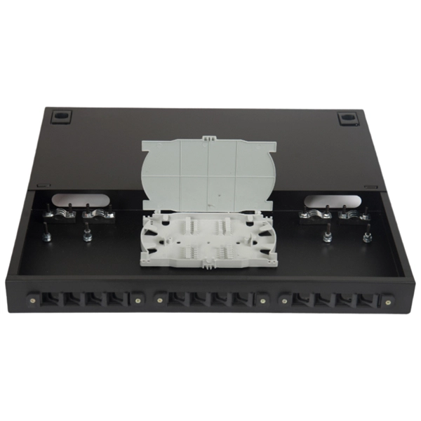
Testing a splitter or other passive fiber optic devices like switches is little different from testing a patchcord or cable plant using the two industry standard tests, OFSTP-14 for double-ended loss (connectors on both ends) or FOTP-171 for single-ended testing. First we should define what these. Splitter loss refers to the reduction in optical power that occurs when a single optical signal is divided among multiple output ports in a fiber optic network. Insertion loss testing of the optical splitter is very important to ensure compliance to the optical parameters of the manufactured. Optical splitters are vital components in fiber optic networks, distributing signals from a single input fiber to multiple output fibers. Here is a table of typical losses for splitters. Signal loss within a system is expressed using the decibel. The CertiFiber® Pro Optical Loss Test Set (OLTS) can be used to check that the loss of a PON Splitter (often referred to in various standards as a non-wavelength-selective or wavelength-selective branching device) to check that it is within the allowed defined limits. The CertiFiber® Pro has an.
[PDF Version]
BS EN 60794-1-21 is maintained by GEL/86/1. The current release of this standard is: BS EN 60794-1-21:2015+A1:2020 Optical fibre cables. Basic optical cable test procedures. Mechanical tests methods This standard is available from the following sources:The International Electrotechnical Commission (IEC) is the leading global organization that prepares and publishes International Standards for all electrical, electronic and related technologies. The technical content of IEC publications is kept under constant review by the IEC. An objective of this document is to define general requirements and methodology. Listing of all FOA standards FOA Standard FOA-1: Testing Loss of Installed Fiber Optic Cable Plant, (Insertion Loss, TIA OFSTP-14, OFSTP-7, ISO/IEC 61280, ISO/IEC 14763, etc. IEC 60794-1-2:2021 applies to optical fibre cables for use with telecommunications equipment. Electrical properties are specified for optical ground wire (OPGW) and optical phase conductor (OPPC) cables.
[PDF Version]
Passive optical networking (PON), like active optical networking, uses fiber-optic cabling to provide Ethernet connectivity from a main data source to endpoints. In practice, PONs are typically used for the last mile between Internet service providers (ISP) and their customers. It uses only optical fibers to transmit data, voice, and video services. A PON network consists exclusively of passive optical components. "Passive" refers to the use of optical fiber cables connected to an unpowered splitter, which in turn transmits data from a service. In a PON access network there are two end-points with active (powered) electronic transmission equipment, connected by passive (non-powered) equipment known as outside fiber plant.
Optical fibers are an integral part of modern communication systems, enabling high-speed data transfer and reliable connectivity. They are thin, transparent strands of glass or plastic used to transmit light signals over long distances. Light acts as a carrier wave and can be modulated to carry information. Fiber is preferred. Recent advancements including coherent detection, optical amplification, and fiber-optic sensing are discussed, along with their impact on future networks.
Directional couplers are multiple-waveguide couplers used for codirectional coupling. They can be used in many different applications, including power splitters, optical switches, wavelength filters, and polarization selectors. We consider in this tutorial two-channel directional couplers, which. Mode division multiplexing (MDM) has provided a new trend in high capacity optical transmission systems.
For such cables, we recommend using at least a 1. It's important to consider not only the rigidity of the jacket but also the breakout point of the assembly, where the strands exit the jacket and are encased in. 8 core single mode fiber optic cable should be selected by fiber mode, core count, cable structure, jacket material, installation route, tensile strength, attenuation test, reel length, and quantity. Selecting the right conduit ensures the cable's longevity, prevents signal degradation, and supports efficient installation and maintenance. They feature low attenuation benchmarks 2 and minimal dispersion. They use OS1 or OS2 OS1 or OS2 classifications to. Understanding the physics behind Single Mode vs Multi‑Mode Fiber is essential for selecting the right conduit for any optical network. Single‑mode fiber (SMF) employs an ultra‑narrow core—typically 8 to 10 µm in diameter—that permits only one propagation mode.
[PDF Version]Contact us for competitive quotes on any of our power communication and smart grid products
Get a Quote