
Patch cables connect the splitter to the equipment, so it's essential to choose high-quality cables for reliable performance. The input/output configuration (1×2, 1×4, etc. A fiber-optic splitter, also known as a beam splitter, is based on a quartz substrate of an integrated waveguide optical power distribution device, similar to a coaxial cable transmission system. The optical network system uses an optical signal coupled to the branch distribution. One component makes PON deployment scalable and efficient: the fiber optic splitter.
A fiber-optic splitter, also known as a beam splitter, is based on a quartz substrate of an integrated waveguide optical power distribution device, similar to a coaxial cable transmission system. The optical network system uses an optical signal coupled to the branch distribution. The fiber optic splitter is one of the most important passive devices in the optical fiber link. It is an optical fiber tandem d. TypesAccording to the principle, fiber optic splitters can be divided into Fused Biconical Taper (FBT) splitter and. Wave splitting involves dividing a light beam into multiple streams. The daughter streams can be equal or in some other ratio. The FBT splitter uses two (or more) fibers. The fibers'. • The FBT splitter offers low cost, common materials (quartz substrate, stainless steel, fiber, hot dorm, GEL), and an adjustable splitting ratio. However, its losses are wavelength-dependent and it offers poor spectral uni. • • • • •.
[PDF Version]
Fusion couplers, made by melting a section of twisted fibers, offer the lowest insertion loss (~0. 3 dB) and highest power handling, with a limited wavelength bandwidth of ±40 nm and polarization extinction ratio below 23 dB. Optical splitters, encompassing FBT (Fused Biconical Taper) couplers and PLC (Planar Lightwave Circuit) splitters, are prevalent passive optical devices designed to divide fiber optic light into multiple segments based on a specified ratio. T PON standards such as GPON, XGS-PON and new 25 and 50G standards. We offer a full line of fiber optic couplers and splitters supporting SM, MM, PM, large core, and double-clad fibers across 300–2000 nm, with power handling up to 100 W and operating temperatures up to 300°C. Three fabrication methods are employed: fusion, micro-optics, and planar lightwave circuit. Carrier-grade standard insert type 1-4 optical splitter, low insertion loss, uniform light splitting 2. Uniform light splitting and stable transmission using high-quality transmission.
[PDF Version]
The maximum split ratio of the FBT splitter is as high as 1:32, which means that one or two inputs can be divided into outputs of up to 32 optical fibers. This guide. There are two different distribution methods of optical splitters in the FTTH network: centralized distribution and cascaded distribution, corresponding to one-stage and two-stage splitting modes, respectively. Each of these splitting methods has its own advantages and disadvantages, which will be. A fiber-optic splitter, also known as a beam splitter, is based on a quartz substrate of an integrated waveguide optical power distribution device, similar to a coaxial cable transmission system. The optical network system uses an optical signal coupled to the branch distribution. This reduces the number of fibers needed between the OLT and the field, as only four feeder fibers are required. Each of the four fibers leaving this stage 1 splitter is routed to an access terminal that houses a 1×8, stage 2 splitter. In this scenario, there would be a total of 32 fibers (4×8) reaching 32 homes.
[PDF Version]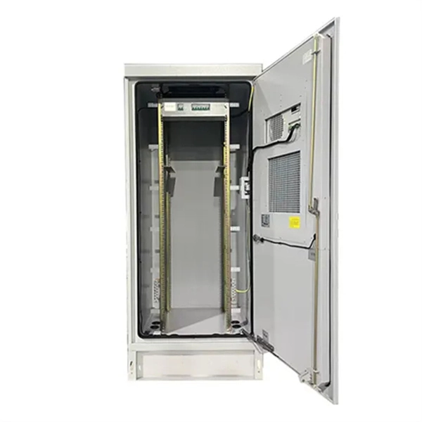
PLC splitters offer a better solution for larger applications. Waveguides are fabricated using lithography onto a silica glass substrate, which allows for routing specific percentages of light. As a result, PLC splitters offer accurate and even splits with minimal loss in an efficient package.OverviewA fiber-optic splitter, also known as a, is based on a of an integrated waveguide power. According to the principle, fiber optic splitters can be divided into Fused Biconical Taper (FBT) splitter and Planar Lightwave Circuit (PLC) splitters. The FBT splitter is one of the most common. F. Wave splitting involves dividing a light beam into multiple streams. The daughter streams can be equal or in some other ratio. The FBT splitter uses two (or more) fibers. The fibers'. • The FBT splitter offers low cost, common materials (quartz substrate, stainless steel, fiber, hot dorm, GEL), and an adjustable splitting ratio. However, its losses are wavelength-dependent and it offers poor spectral uni.
[PDF Version]
This guide walks through a practical, real-world installation process used in FTTH deployments. It covers not only mounting and splicing, but also how to plan port capacity, manage slack, label correctly, and avoid common installation mistakes. Fiber closure protects spliced fibers in backbone and feeder lines, fiber box (or fiber distribution box) organizes and splits fibers in communities or buildings, and fiber terminal box provides the final termination for indoor drop cables. Understanding how these devices work together helps. Terminal boxes are suitable for a dispersed network structure after deploying the optical splitter. They are composed of fixed cable components, splitter modules, fusion splicing modules, storage areas and more. Installing a fiber optic termination box is one of those jobs that looks simple on paper, but it's easy to do poorly in the field.
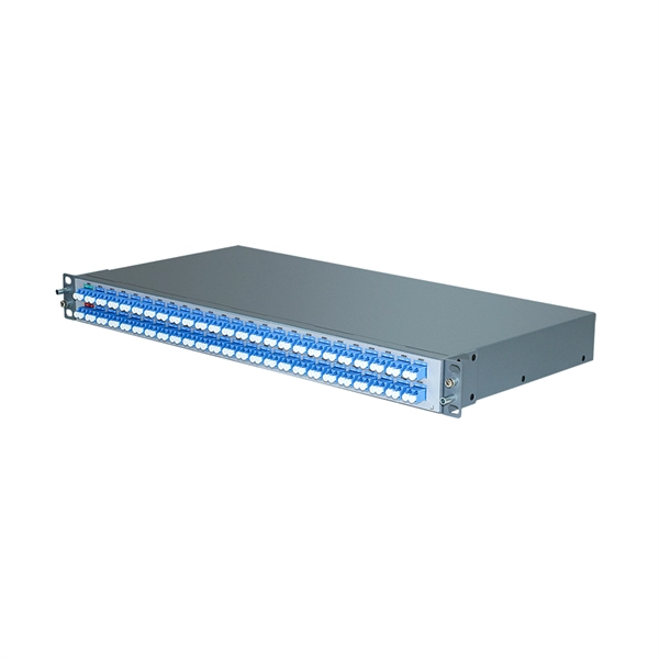
For example, in a typical FTTH deployment, a central ** 1×32 PLC splitter ** can serve up to 32 households from a single fiber line. This not only reduces the amount of fiber cabling required but also lowers installation and maintenance costs. A typical split ratio in a PON application is 1:32, meaning one incoming fiber split into 32 outputs. High-Performance / Business: You might limit a 1:32 panel to only 16 active. For example, a 1:32 splitter takes 1 input signal and splits it into 32 equal (or nearly equal) output signals. Key factors include precise engineering, minimal insertion loss, durability in extreme temperatures, proper. The use of optical splitters in PON allows the service provider to conserve fibers in the backbone, essentially using one fiber to feed as many as 64 end users.
A fiber-optic splitter, also known as a, is based on a of an integrated waveguide power distribution device, similar to a The system uses an optical signal coupled to the branch distribution. The splitter is one of the most important in the link. It is an optical fiber tandem device with many input and output terminals, especially applicable to a passive optical network (,,,.
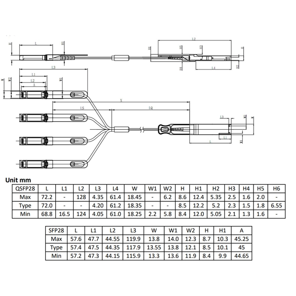
The SFP-10G-AOC SFP+ Active Optical Cable is a plug-and-play, cost-effective solution for 10Gbps connections. It uses Multi-Mode Fiber (MMF) with SFP+ connectors and has built-in optics, eliminating the need for separate transceivers and patch cables. A 10G SFP+ AOC offers a straightforward, high-performance means of interconnecting two 10-gigabit ports—efficiently and without the complexity of separate optics and fiber. The overview below explains the essentials in clear terms. This AOC is compliant with SFF-8431 MSA standards. Key characteristics include: Integrated Optics and Electronics: Embedded transceivers at both ends handle conversion between electrical 10 GbE signals. A MANUFACTURER - 14 years ISO certified manufacturer, assembly SFP transceiver, fiber patch cords, media converter and networking system. ESD This transceiver is specified.
Contact us for competitive quotes on any of our power communication and smart grid products
Get a Quote