
The formula is simple: sum the cross-sectional areas of all cables inside the conduit, divide by the conduit's inner area, multiply by 100. Use this calculator to estimate total optical attenuation across your network and confirm system performance against recommended design margins. The tool accounts for fiber attenuation, connector and splice losses, splitters, and other passive components, helping ensure reliable transmission in. A tool that computes how many fibers fit in a circular bundle and splits them into user-defined segments for cable-assembly planning. Key Parameters: • Center Diameter, Fiber Diameter, Packing Efficiency, Section Count Calculation: Visualization: • Color-coded radial diagram with per-section. Fill ratio — sometimes called fill percentage — is the ratio of the total cross-sectional area occupied by cables to the interior cross-sectional area of the conduit, expressed as a percentage.
[PDF Version]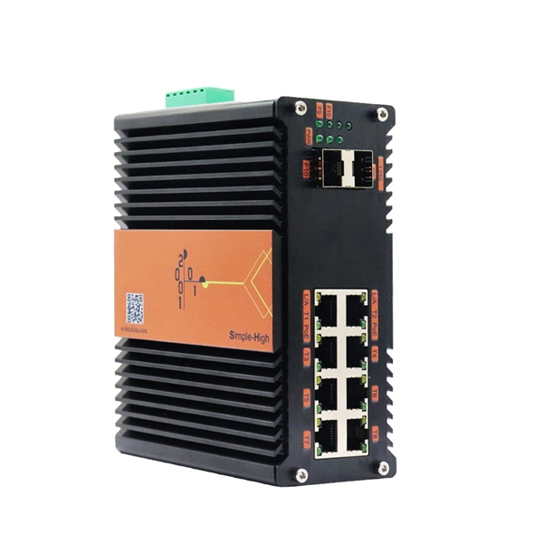
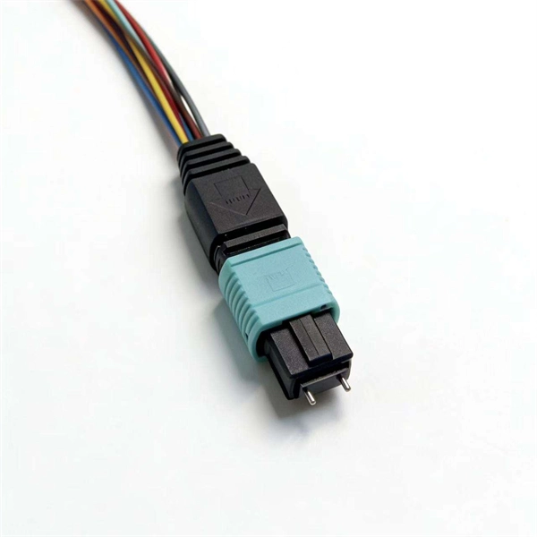
A fiber optic distribution box, also known as a fiber optic terminal box or fiber optic termination box, is a device used to connect and manage fiber optic cables in a network. Its primary function is to provide safe and reliable connection, distribution, and. A distribution box serves as a critical component in fiber optic networks. These cables are used mainly for digital audio connections between devices.
An Optical Distribution Frame (ODF) is the central hub of your fiber optic network. From a planning and design perspective, this article will give you an organized understanding of the meaning, function, and differences between the three most frequently used fiber optic components.
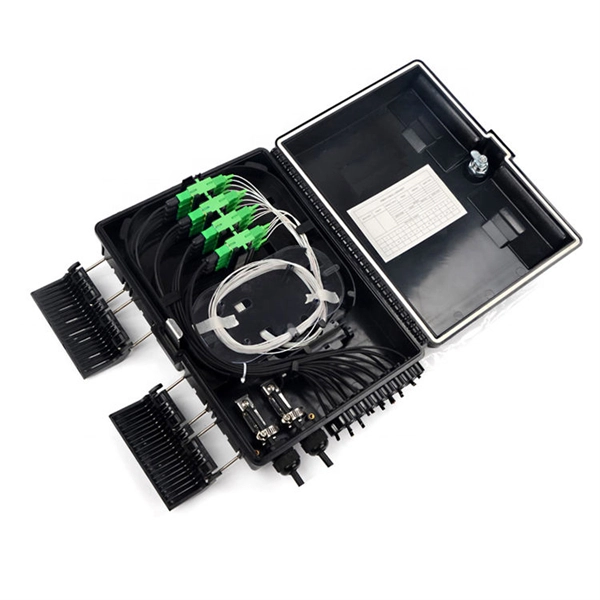
48 Port Fiber Distribution Box provides 16, 24, 32 or 48 SC ports in a traditional two-layer design – a rear splice area for cable slack and splice protection, and a front interconnect area for SC ports. Here are some common types of 48-core optical fiber distribution boxes. These boxes are meant for use inside buildings. They help manage and distribute fiber optic cables for things like internet systems, phone. 48 Core Distribution Box-Fiber Optic Distribution Box-Optical Passive Products-Products-PLC Splitter,Fiber Optical Receiver,Fiber Optical Distribution Box HANGZHOU DAYTAI NETWORK TECHNOLOGIES CO. It offers cable management features, such as splice tray placement, to ensure proper management of fiber optic cables and splices.
This box integrates fiber splicing, splitting, distribution, storage, and cable connection into a single unit. Fiber distribution box is suitable for the wiring connection of optical cable and optical communication equipment, through the adapter in the wiring box, the optical jumper leads the optical signal, and realizes the optical wiring function. With its total enclosed structure. The JUNPU 4 fiber drop box is a light and compact wall-mountable enclosure for the termination of up to four fibers. 4 Cores Fiber Distribution Box IP-55 SC Connector PLC Splitter FDB-104B Fiber Distribution box (FDB), known as optical Distribution box (ODB) as well, is a compact fiber management product of small size. It is typically used in cabling work area subsystems.
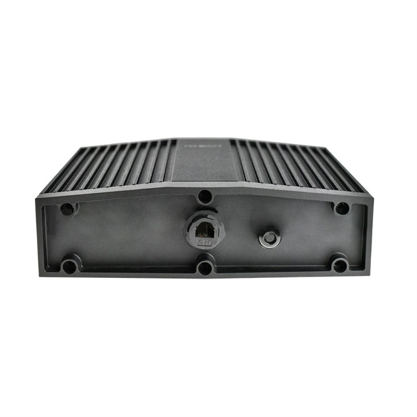
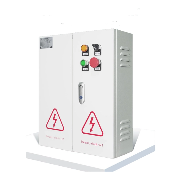
Grounding of the units: Attach a ground wire from one of the threaded studs (A) at the bottom of the housing, to the mounting plate (B). The ground resistance between all system parts. This Applications Engineering Note (AE Note) discusses conventional bonding and grounding practices for conductive fiber optic cable and hardware installations within the scope of the National Electrical Code (NEC). Each DISTRIBUTION BOX and controller must be grounded. 26 mm 2 (10 AWG) ground wire must be used, and in all other markets a 6 mm 2 must be used. It can also be deployed in any cross-connect architecture and still provide clear, managed pathways for fiber. Whether you're a seasoned pro or just starting out, this comprehensive guide will give you practical. Our handbooks show you how to build fibre or copper infrastructure at your new residential or commercial development, and how to install Openreach equipment. Therefore, proper grounding is essential.
[PDF Version]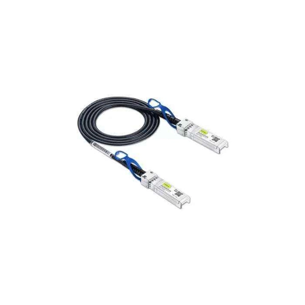
Optical cable distribution boxes are essential components in modern telecommunications infrastructure. They serve as hubs where fiber optic cables are connected, managed, and distributed to end-users. As digital connectivity demands grow, these boxes are becoming more versatile and. Wherever glass fiber connections have to be installed in a harsh environment - in offices, industry or Fiber-to-the-Building/-Home customer access networks - high demands are made on the value and flexibility of the distributor housing and easy access whilst installaton and maintenance. As the junction point for fiber terminations and splicing, the FDB ensures signal integrity, simplifies maintenance, and protects delicate fibers from environmental hazards.
Full-spectrum single-mode fibre in accordance with ITU-T G. D with optimised transmission characteristics. 652 fibre was originally optimized for use in the 1310 nm wavelength region but can also be used in the 1550 nm region. a number of concatenated cable. “Leviton is dedicated to designing, developing and manufacturing sustainable high performance structured cabling and specialty cabling solutions. ” The information contained in this document is valid and correct at the time of issue. 1dBNote: Due to OTDR measurement uncertainty B3 International cannot guarantee attenuation values at fibres shorter than 1000m. Specifications are for product as supplied by Prysmian: any modification or alteration afterward of product may give different result.
The FDB-12E 12 Core Optical Fiber Distribution Box is used as a fiber access and distribution point for terminating, splicing, splitting, and managing optical fibers between feeder cables and drop cables. It supports organized fiber management for FTTH, FTTx, and building access. 12 Core FDB Fiber Optic Distribution Box With PLC Splitter Description: Optic Fiber Terminal Closure optic provides space and protection for the fiber optic cable splicing and joint. A durable 12-core fiber distribution box (225x200x65mm) in ABS/PC+ABS for secure wall or pole mounted FTTH networks.
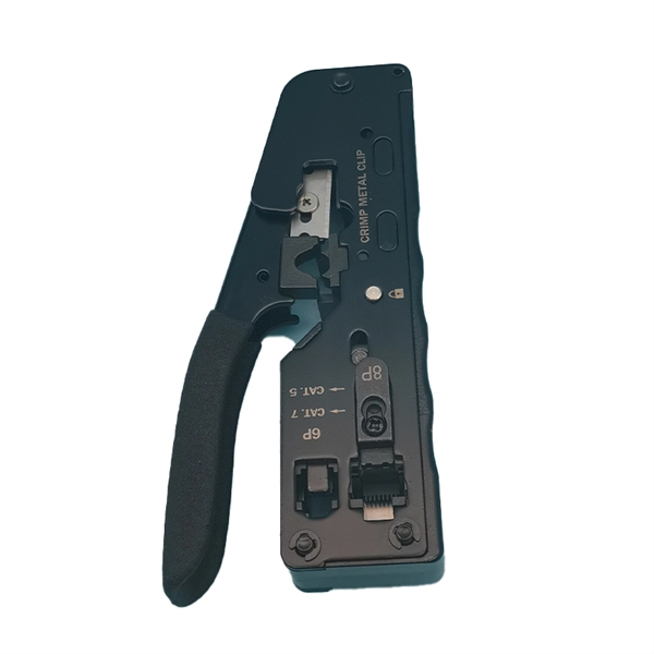
Splice the Pigtail:Fusion-splice incoming fiber to pigtail inside the box. Test:Verify light levels: -27 dBm to -8 dBm (GPON ideal). This guide provides a comprehensive overview of how to choose the right equipment, correctly install fiber and network cables, and optimize network settings to ensure reliable and efficient connectivity. 1G/10G SFP+: Standard for Gigabit and 10 Gigabit Ethernet. Fiber Optic Terminal. Step 1: Access outdoor fiber optic cables into fiber terminal box for the purpose of splicing the optical fiber cable and fiber optic pigtail, leading out it by using fiber optic patch cable. Good quality fiber laying and termination systems help achieve minimal back reflection and low signal loss.
Contact us for competitive quotes on any of our power communication and smart grid products
Get a Quote