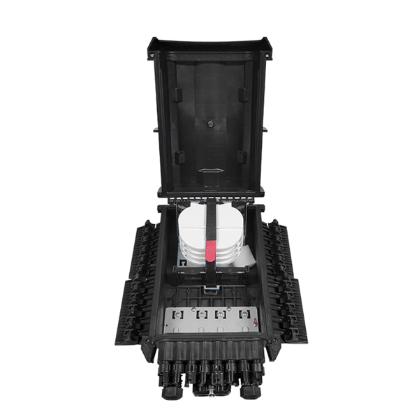
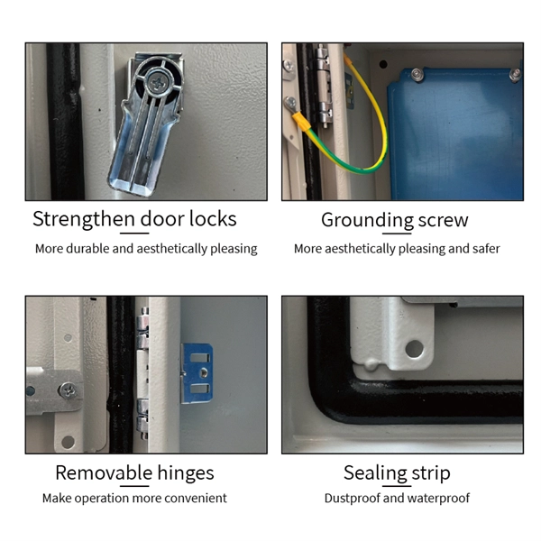
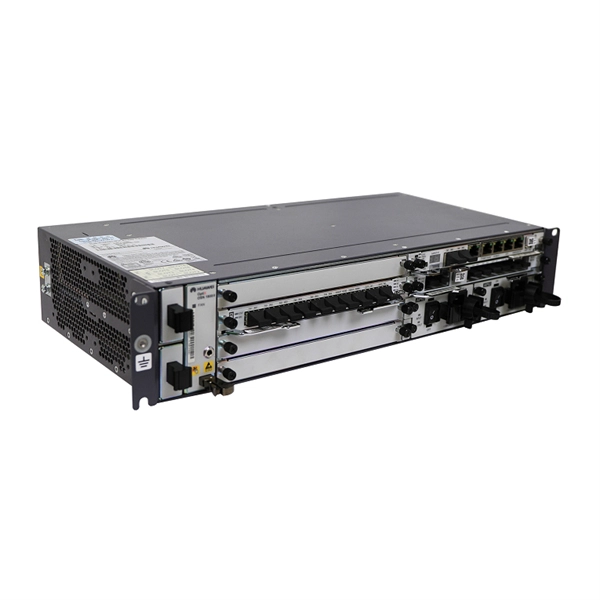
A direct-melting type 1152 core optical cable distributing box is characterized in that a base is arranged at the bottom of a box body of the optical cable distributing box, a bottom plate and optical cable fixing units are arranged in the box body, the bottom plate. A direct-melting type 1152 core optical cable distributing box is characterized in that a base is arranged at the bottom of a box body of the optical cable distributing box, a bottom plate and optical cable fixing units are arranged in the box body, the bottom plate. The optical fiber distribution box is to protect the connection point where the optical cable is connected to the user end, so that the optical cable access point is stable, dustproof and waterproof. Minimize the interference of the optical cable access signal to the external environment. The. The utility model relates to a directly melt type 1152 core optical cable distributing box is limited to the core number in solving current like product, the difficult setting that reaches the 1152 core, and directly melts the not good enough technical problem of unit structure design. The bottom. The main components and general architecture of the FTTH network at any telecom operators include the Optical Line Terminal (OLT), Optical Distribution Frame (ODF), Passive Optical Splitter (POS), Fiber Distribution Terminal (FDT), Fiber Access Terminal (FAT), Fiber Terminal Box (FTB), Optical. The optical cross-connection Cabinet short for OCC, or some other place call it Optical Distribution Cabinet (ODC) or Fiber Distribution Terminal (FDT), is a device designed for indoor/outdoor cable management. generally the OCC/ODC/FDT consists of several part, like integrated splicing unit, PLC. This complete guide explores everything you need to know about ODFs — from their structure, types, and key components, to installation best practices and modern design trends. Whether you're building a central office, data center, or FTTx distribution network, understanding the right ODF. Fiber Distribution box (FDB), known as optical Distribution box (ODB) as well, is a compact fiber management product of small size.