
Testing a splitter or other passive fiber optic devices like switches is little different from testing a patchcord or cable plant using the two industry standard tests, OFSTP-14 for double-ended loss (connectors on both ends) or FOTP-171 for single-ended testing. First we should define what these. Splitter loss refers to the reduction in optical power that occurs when a single optical signal is divided among multiple output ports in a fiber optic network. Insertion loss testing of the optical splitter is very important to ensure compliance to the optical parameters of the manufactured. Optical splitters are vital components in fiber optic networks, distributing signals from a single input fiber to multiple output fibers. Here is a table of typical losses for splitters. Signal loss within a system is expressed using the decibel. The CertiFiber® Pro Optical Loss Test Set (OLTS) can be used to check that the loss of a PON Splitter (often referred to in various standards as a non-wavelength-selective or wavelength-selective branching device) to check that it is within the allowed defined limits. The CertiFiber® Pro has an.
[PDF Version]
FOA procedures, such as OFSTP-7 (single-mode) and OFSTP-14 (multimode), align with TIA and IEC standards. Fiber Optic Testing Testing is used to evaluate the performance of fiber optic components, cable plants and systems. As the components like fiber, connectors, splices, LED or laser sources, detectors and receivers are being developed, testing confirms their performance specifications and helps. ondition of the cabling system and its components with an op cal time domain reflectometer (OTDR). The condition of the fibre end fac g with an OLTS and an OTDR and have obtained a certificate as proof thereof shall execute the tests. 11 Optical Fiber Systems Subcommittee and published in September, 2022. They describe how to set a '0 dB' reference, control mode power distribution, and use proper wavelengths.

This document discusses the commissioning process and tests for various electrical equipment, including current transformers, voltage transformers, circuit breakers, isolators, switchgear, busbars, cables, and protection relays. High voltage and low voltage complete sets occupy a significant place in modern electrical engineering as they are responsible for safe, secure, and efficient power distribution to all types of industries. They are known as complete switchgear assemblies because they integrate inside them such. Senior Electrical Engineer, with 12 years of experience in high and low voltage switchgear installation, commissioning, and overseas project technical support. Currently, Thor is the Technical Department Manager at Weisho Electric Co. ISS have dedicated teams of Power Installation specialists working nationwide fitting out electrical substations, compounds, control rooms and. Electrical commissioning is a critical phase that verifies all electrical systems and components, ensuring they operate safely and reliably under real-world conditions. It's about proving that every system functions as designed, under.
[PDF Version]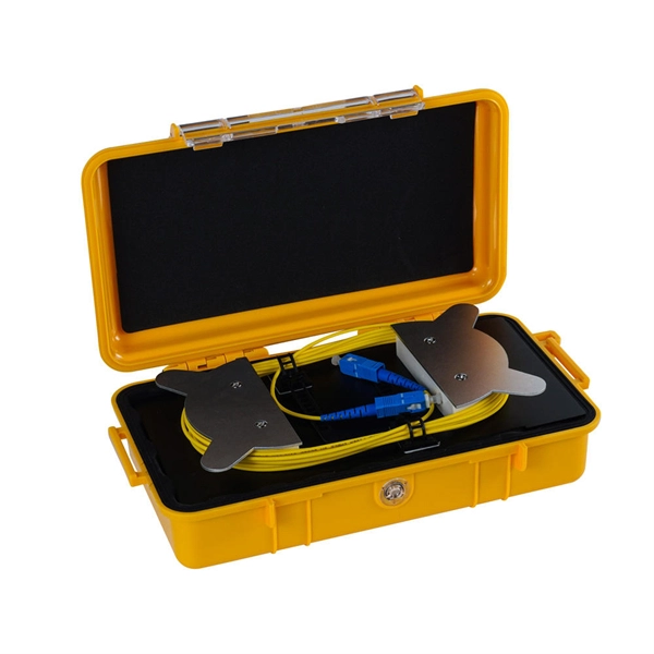
The loss value of a pigtail connector and its associated splice with matching mode field diameters should not exceed 0. Pigtail traces for all. at system. Corning recommends that all fiber optic systems be tested to a minimum set of standards. So, you drop everything and i vestigate. FOA standards align with IEC and TIA, giving you clear steps to earn trusted certification. No part of this book may be reproduced or utilized in any form or means, electronic or mechanical, including photocopying, recording, or by any information storage and retrieval system, without pe n optical fiber to a distant receiver. The electrical signal is. To be able to judge whether a fiber optic cable plant is good, one does a insertion loss test with a light source and power meter and compares that to an estimate of what is a reasonable loss for that cable plant.
Testing a splitter or other passive fiber optic devices like switches is little different from testing a patchcord or cable plant using the two industry standard tests, OFSTP-14 for double-ended loss (connectors on both ends) or FOTP-171 for single-ended testing. Optical splitters are usually used in passive optical networks (PONs) to distribute fiber to individual homes or businesses. In this. Testing networks with both an optical loss test set (OLTS) or OTDR is covered in other pages on Testing FTTH PONs and Testing Passive OLANs. This note also provides background information on system link configurations, test equipment and system component considerations that influence. In fiber optic networks, particularly in FTTx (Fiber to the x) and PON (Passive Optical Networks) deployments, splitters play a central role in distributing the optical signal from a single source to multiple destinations.
[PDF Version]
3‑E “Optical Fiber Cabling and Components Standard” was developed by the TIA TR‑42. The International Electrotechnical Commission (IEC) and the Telecommunications Industry Association (TIA) create detailed rules for fiber optic components, manufacturing, and testing. Scope: This Standard specifies performance, transmission, and test and measurement requirements for premises optical fiber cable. International standards for optical connectors are developed by the International Electrotechnical Commission (IEC). Fiber optic assemblies are unforgiving. Unlike copper wire harnesses where a slightly imperfect crimp might still conduct electricity, a contaminated fiber end face or improper splice can completely block light transmission. These standards ensure interoperability across manufacturers, regions, and applications.
The IEC has published a new standard for the testing of fibre optic cabling. IEC 61280-4-5 provides test methods to measure the attenuation of installed multimode and single-mode optical fibre cabling plant as well as the determination of their polarity and length. They explain how to avoid common mistakes, clarify test reference methods, and provide visual guides. As the components like fiber, connectors, splices, LED or laser sources, detectors and receivers are being developed, testing confirms their performance specifications and helps. IEC 60794 is the international standard series governing the design, construction, and performance verification of fibre optic cables. Fiber optic testing of a newly installed system not only verifies that the system meets its design requirements, but also creates a performance baseline for all future testing and troubleshooting of t at system. Corning recommends that all fiber optic systems be tested to a minimum set. We offer full-service OEM and ODM solutions for fiber optic cables, assemblies, and connectivity products — from design and prototyping to global production and logistics.
[PDF Version]
Once installed, the splitter simply becomes one source of loss in the cable plant and is tested as part of that cable plant loss for insertion loss testing. First we should define what these. Here Kingfisher's experienced engineers share their experience in best practices and procedures for fiber optic testing related mostly to installation and maintenance. We hope that by sharing our knowledge, we will help grow our industry. Please enjoy & pass on these notes. Other Passive Devices There are other passive devices that require testing. Insertion loss testing of the optical splitter is very important to ensure compliance to the optical parameters of the manufactured splitter in accordance with the GR-1209 CORE specification. Signal loss within a system is expressed using the decibel. In fiber optic networks, particularly in FTTx (Fiber to the x) and PON (Passive Optical Networks) deployments, splitters play a central role in distributing the optical signal from a single source to multiple destinations.
[PDF Version]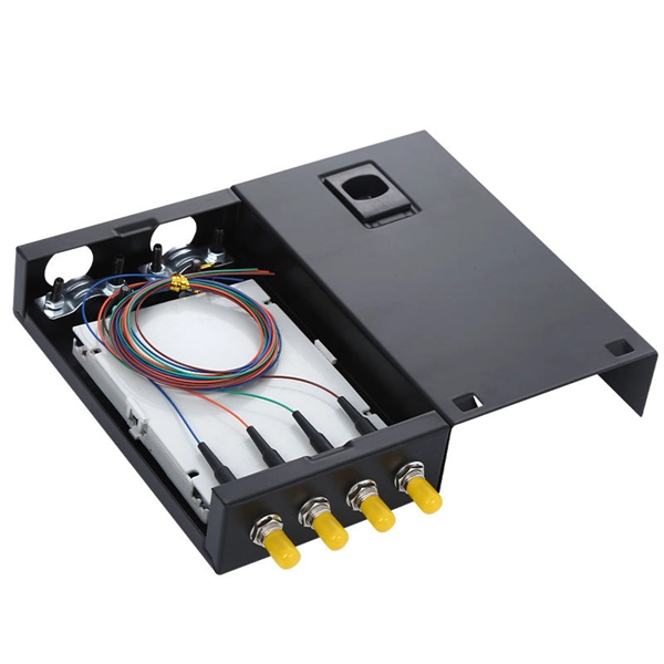
This document outlines the procedure recommended by Panduit for field permanent link loss testing of multimode and singlemode structured cabling systems. It simply means a reduction in optical power, for example the loss caused by a component or an entire cable. The component could be a length of fiber, a splice, a connection made between two connectors or a passive component like an. FOA "Quickstart Guides" are short, simple guides to basic fiber optic tests. References to FOA "1. Launch Fibers are packaged in a rugged, convenient zipper case, designed for use with our T-Pak magnetic / hanger / hook and loop strap. Also known as launch packs or Dead Zone Eliminators used for OTDR (Tier II) testing Fluke Networks Test Reference Cords and Launch Fibers with LC connectors. This Applications Engineering Note (AEN 135) explains and recommends standard measurement methods for characterizing optical fiber system performance.
[PDF Version]Contact us for competitive quotes on any of our power communication and smart grid products
Get a Quote