
Differential protection relays are widely used for busbar protection. They operate based on the principle of comparing the currents entering and leaving the busbar. A busbar protection is a protection to protect busbars at short-circuits and earth-faults. Index Terms—Breaker failure protection, bus, check zone, cur-renttransformers,differentialbusprotection,dynamicbusreplica, electric power substation, high impedance differential, partial dif-ferential. Your mission is to protect that busbar and one of the customer requirements says that they prefer either a SEL-487B or a SEL-587Z relay for this job. The relay can also be utilized.
The IEC 61439-1 sets the thermal limit in busbars working at the maximum working load. Here, 140°C (which is 105K over the ambient temperature of 35°C) is the upper safe temperature limit. Continuous, real-time busbar temperature monitoring and hot spot detection for MV & HV switchgear, substations and power plants — EMI-immune, calibration-free, fully SCADA-integrated. Thermal monitoring locations include: Eaton Exertherm CTM solution for MV switchgear. Standards mandate that busbars, when carrying their rated continuous current for extended periods, must not experience excessive temperature rise.
Some early busbar protection configurations applied a low impedance differential system that has a relatively long operation time, of up to 0. The foundation of most modern configurations is a differential system using either low impedance biased or high impedance. The choice of protection technique used for a specific busbar depends on the protection requirements for speed and security, balanced against the cost of implementing a specific solution, and the operating requirements for a specific bus. In the early days of power system development no separate protection device was used for busbar protection. Remote end-line protections served as the main. This comprehensive guide explores the technical requirements, installation best practices, and protection coordination strategies for MCCB-busbar connections. Whether you're designing a new switchgear assembly or maintaining existing distribution panels, understanding proper connection methods. segregated short-circuit protection, control, and supervision of single busbars.
[PDF Version]
ABB's busbar protection is designed for phase-segregated short-circuit protection, control, and supervision of single busbars. GE Multilin provides protective relays that support all busbar protection techniques, including overcurrent, high-impedance differential, and percentage (low-impedance) differential. Current Differential Protection: This protection method connects CT secondaries in parallel and. This article discusses a software based substation protection, automation, and control system (PACS), iSAS, developed by LYSIS LLC, Russia which is was at that time under trial operation at the 110/10 kV “Olympic” substation in the town of Surgut in northwest Siberia. The philosophy of iSAS is. A busbar is a strip or bar of copper, brass or aluminum that conducts electricity within a switchboard, a substation or a battery bank. Its purpose is to conduct a substantial current of electricity.
[PDF Version]
This study proposes a protection relay using a microcontroller to detect and classify faults in transmission lines based on the wavelet transform. nsform with differential protection scheme. The current signal was observed based on the fault type. Abstract— This paper gives a review of the use of wavelet transform for protection of transmission line. For a modern power system, selective high speed clearance of faults on excessive voltage transmission line is essential and this review indicates the efficient and promising implementations for. This paper presents the novel approach in protection and detection techniques of Alternator stator winding from the earth faults which are simulated between 2% to 10% distance point from the alternator neutral, since the impedence at that distance is very high we can not detect or protect by normal.
A comprehensive protection relay (or integrated protection relay) is a smart electrical device that combines multiple protection functions to monitor power systems (e., generators, transformers, motors, transmission lines) and quickly isolate faults to ensure safety. It features modular. IEEE/IAS/I&CPSD Protection & Coordination WG Chair Jacobs Canada, Calgary, AB rasheek. Currently residing in Denver, Colorado. Previous experience in designing low voltage and medium voltage switchgear, relay panels and custom control panels as an Electrical Engineer at ESSMetron, Denver CO. SIPROTEC 7SD80 delivers selective line protection for power cables and overhead lines up to 24 km, supporting all starpoint configurations.
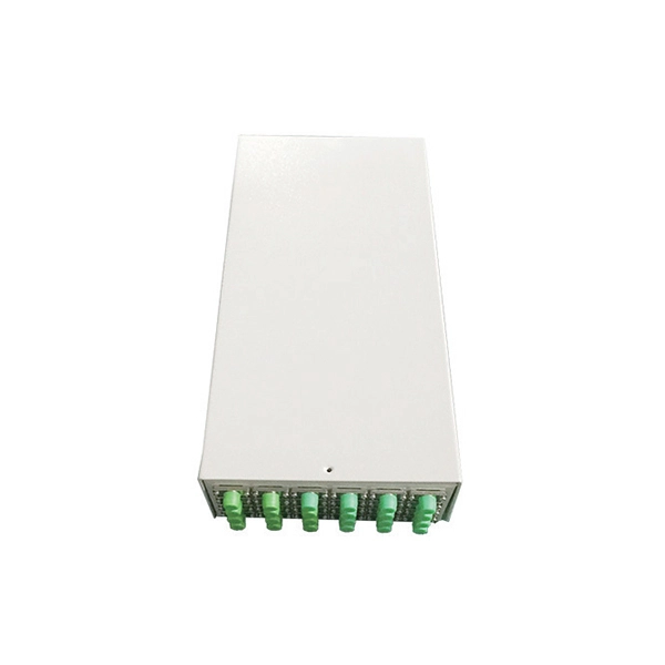
Products include fiber raceway system, vertical and horizontal cable managers (finger) in metal/plastic and cable management rings. Recloseable storage rings are used for optical fiber and copper cabling service loops. The Fiber Channel System is designed to protect and route the fiber. Fiber rings refer to configurations or architectures used in fiber optic networks, often employed in telecommunications to ensure high-speed data transmission with redundancy and reliability. Understanding fiber rings and related terms is crucial for anyone involved in network design. Key factors include material durability, bend radius compliance (typically ≥30mm), mounting method (snap-in, adhesive, or rack-mounted), and compatibility with existing racks or panels. Ring shall have "hook and loop" style loops to contain and secure cable.
This guide provides a comprehensive overview of various transformer protection schemes and offers recommendations for relay selection, coordination, and settings. Another important standard is the IEC 61850, which focuses on communication protocols for substation automation systems. Table 1 – Transformer fault types/protection methods 1. In HV (High Voltage) and MV (Medium Voltage) substations, relay protection safeguards critical assets such as transformers, circuit breakers, and lines. • If current penetrates the limits of the thermal damage curve, insulation damage may occur.
Contact us for competitive quotes on any of our power communication and smart grid products
Get a Quote