

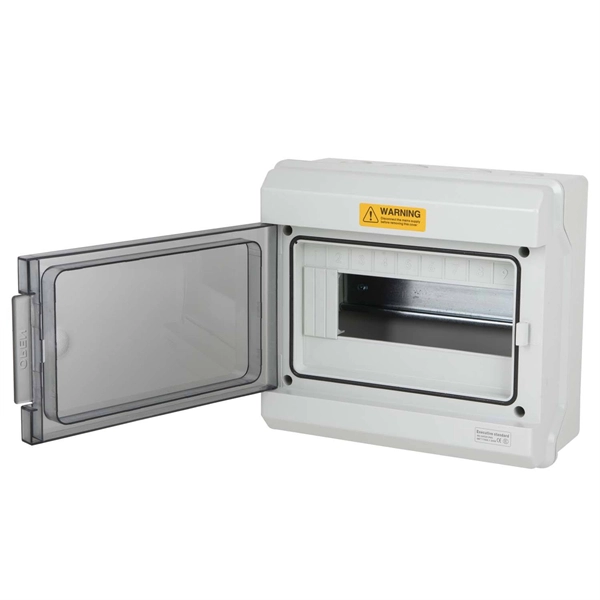
The ideal structure for connecting two fiber cables is as follows: Cable A → Adapter Panel → Patch Cord → Adapter Panel → Cable B How It Works Fiber Adapters: Bridge the two connector types (e., SC to LC, or SC to SC). Patch Cords: Provide a short, flexible link between adapters. To connect two optical fibers together, a process called splicing is used. This involves aligning the two fiber ends and then fusing them together using heat or a specialized tool. Fiber cabinets, patch panels, and distribution frames are designed to manage and protect terminations, not for direct splicing. Data Servers are at Location A.
Connect the opposite end of the cable into the single end of the fiber optic cable splitter. Installing a fiber optic splitter involves several crucial steps to ensure proper functionality and reliability. Here's a step-by-step guide to help you through the process: Identify Requirements: Determine the type of fiber optic splitter you need based on your network's specifications, such as. This video provides a step-by-step guide on how to efficiently install optical splitter into a fiber terminal box, demonstrating a professional and reliable deployment for optical distribution network solution ( https://www. Indoor options encompass locations like the community's central computer room, building's weak current well, or floor wiring box.
100 describes characteristics, construction, test methods, and performance criteria of optical fibre cables installed by pulling method for duct and tunnel application. Note that Recommendation ITU-T L. Electrical properties are specified for optical ground wire (OPGW) and optical phase conductor (OPPC) cables. 0, in February. This standard BS EN IEC 60794-1-209:2024 Optical fibre cables is classified in these ICS categories: IEC 60794-1-209:2024 defines test procedures to be used in establishing uniform requirements for the environmental performance of: - optical fibre cables for use with telecommunication equipment and. The International Electrotechnical Commission (IEC) is the leading global organization that prepares and publishes International Standards for all electrical, electronic and related technologies. The technical content of IEC publications is kept under constant review by the IEC.
[PDF Version]
Connect Switch with a corresponding fiber device through a fiber cable, or connect with a Media Converter and change to electrical signal for output. Users could choose to use the SFP fiber port or electrical port of the Switch according to different conditions;Equipped with eight SFP+ ports, two additional SFP28 ports and one RJ45 console port for configuration. With AXIS D8308 Fiber Aggregation Switch you can connect multiple Axis devices using fiber midspans over long distances. Simply put, it defines how network. This article reviews essential features as well as benefits and technical specifications associated with an 8 port sfp optical switch, thus giving you a complete idea of how it works in modern networking environments. Whether you work as an IT professional or have an interest in technology only. This SR8 multimode, parallel, 8-channel transceiver uses two, 4-channel MPO-12/APC optical connectors at 400Gb/s each. The parallel multimode, short reach 8-channel (2xSR4) uses 100G-PAM4 modulation and has a maximum fiber reach of 50-meters using 8 multimode fibers. Cisco Catalyst 1000 Series switches provide support for the.
[PDF Version]
The ideal structure for connecting two fiber cables is as follows: Cable A → Adapter Panel → Patch Cord → Adapter Panel → Cable B How It Works Fiber Adapters: Bridge the two connector types (e., SC to LC, or SC to SC). Patch Cords: Provide a short, flexible link between. To connect two optical fibers together, a process called splicing is used. Fusion Splicing: This method involves aligning the ends of the two fiber optic cables and then fusing them together using heat. This creates a permanent and low-loss connection. ►Optical Cable Splitter : https://amzn. As a leading provider of fiber optic solutions, Weunion offers a wide range of SFP-compatible products, including optical transceivers, DAC/AOC cables, LC patch cords, and MPO/MTP assemblies.
A simple solution is to combine a Corning USB “A to receptacle-A” USB 3. Optical™ Cables by Corning with a short, off-the-shelf jumper cable that has a USB “A” plug on one side and the particular connector your end device requires on the other. 0 A female port of the AOC Cable. Vielen Dank für den Kauf dieses Optischen USB 3. Es unterstützt größere Distanzen als herkömmliche Kupferkabel, ist deutlich flexibler und leichter und daher optimal. A workaround would be to connect the USB 3. Once connected, check the Windows Device Manager to verify the devices that have been successfully connected through the device. The USB active optical cables are designed to be compliant with SuperSpeed USB and SuperSpeed+ USB electrical specifications, offering seamless interoperability between existing USB 3. 1 hosts, hubs and devices, ensuring a trouble-free plug-and-play experience. The USB AOC address the. Connect the USC-CC32 Type C device connector to the USB Hub.
[PDF Version]
Short answer: Usually yes, you use them in pairs, but the “pair” can be a media converter on one end and a fiber switch (or SFP in a switch) on the other, as long as both sides speak the same speed, wavelength, and optical mode. The term "single/dual fiber" refers to how many fiber strands are used for communication between two devices. Single fiber modules—often called bidirectional (BIDI) transceivers—transmit and receive signals over a single optical fiber by using two different wavelengths. For example, one module. The secret lies in fiber optic technology, and understanding the basics—1-core, 2-core, Single Mode (SM), and Multi-mode (MM)—is key to mastering this field. Let's break down these terms in simple, clear language with practical examples. In DWDM implementations, each direction of communication occupies a dedicated fiber, improving the stability of the transmission. Understanding the compatibility constraints prevents costly downtime and troubleshooting.
[PDF Version]
A hybrid fiber optic cable is a composite cable that integrates traditional glass optical fibers for data transmission with copper wires for electrical power. This innovative design eliminates the need to install separate cables for data and power, streamlining complex deployments. As I step into my new role as Vice President and General Manager of Emerging Businesses & EMEA, I'm especially excited to highlight Corning's newest future-agile innovations at the 2026 Optical Fiber Communication Conference and Exposition in Los Angeles., May 12, 2026 / PRNewswire / -- 3M (NYSE: MMM) today announced it has joined a group of leading technology companies to establish a new multi-source agreement (MSA) focused on advancing open, interoperable specifications for expanded beam optical (EBO) connectivity in AI infrastructure.
Contact us for competitive quotes on any of our power communication and smart grid products
Get a Quote