
Fusion splicing is most widely used as it provides for the lowest loss and least reflectance, as well as providing the most reliable joint. Virtually all singlemode splices are fusion. Fiber optic joints or terminations are made two ways: 1) splices which create a permanent joint between the two fibers or 2) connectors that mate two fibers to create a temporary joint and/or connect the fiber to a piece of network gear. For network managers and technicians, a poor splice can lead to significant signal degradation, network downtime, and costly troubleshooting. There are numerous use cases for fiber optic splicing. As. Splicing fiber optic cable is an extremely important phase for making dependable, high-speed communication infrastructures. Regardless of the type of fiber network you're deploying, be it for telecom, enterprise data centers, or smart city infrastructure, fusion splicing provides the benefits of. Splicing is most commonly used in the field but has application in cable assembly houses.
[PDF Version]
Unlike a patch cord—which has connectors on both ends—the bare fiber end of a pigtail is designed to be permanently spliced (either by fusion or mechanical splicing) to the incoming fiber cable in the field. Get the wrong connector type, the wrong polish, or skip proper fusion splicing technique—and you're looking at elevated signal loss, increased back reflection, and a. A fiber pigtail is a short length of optical fiber that comes with a high-quality, factory-polished connector already installed on one end, leaving a length of exposed glass on the other. Consequently, technicians can achieve lower insertion loss and better performance compared to field-terminated connectors.
A pigtail is used to provide fiber optics with a connector. This creates a stable and reliable. Fiber pigtails are simple in appearance, yet essential in function. They are the bridge between fiber optic cables in the field and the equipment or patch panels that manage them. Get the wrong connector type, the wrong polish, or skip proper fusion splicing technique—and you're looking at elevated signal loss, increased back reflection, and a. A fiber optic pigtail is a short optical fiber cable that has a connector on one end and an exposed (unterminated) fiber on the other.
An Optical Power Meter and Laser Light Source will be used to measure power loss on each completed ring or distribution span to verify continuity between fibers (no fibers incorrectly spliced together). Fiber optic testing for continuity is crucial in ensuring that light transmits through fiber optic cables without interruptions, safeguarding seamless data transmission. Fiber optic. Fiber testers provide the precision needed to install, certify, and maintain high-speed optical networks. This category includes OLTS certifiers, OTDRs, optical power meters, light sources, and visual fault locators. For more information about FiberLert™ Live Fiber Detector, click here. Fiber QuickMap mainframe with SC/LC 50 µm Launch Fiber and carrying pouch. Our unique and innovate MPO Visual Cable Verifier Kit is versatile, inexpensive, and practical.
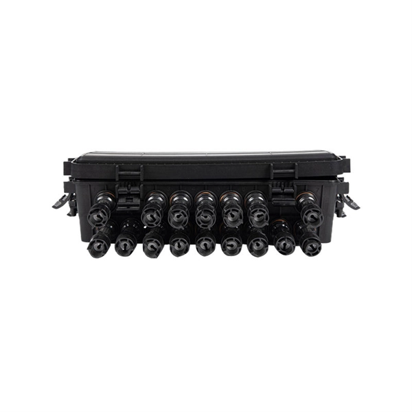
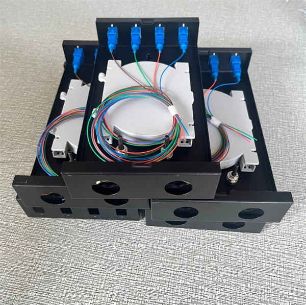
Fusion splicing uses a precision arc discharge between two electrode rods to heat and fuse the cleaved fiber ends together. When done correctly, the splice point becomes essentially seamless—the glass of the two fibers melts together into a single, continuous strand. Executive Summary: A fiber optic pigtail is one of the most commonly specified yet least understood components in structured cabling. Get the wrong connector type, the wrong polish, or skip proper fusion splicing technique—and you're looking at elevated signal loss, increased back reflection, and a. Fusion splicing is the backbone of modern fiber optic installations—and it's the primary method used when working with fiber optic pigtails. This. Fiber optic fusion splicing is on the rise and Corning's Pigtailed Splice Cassettes enable faster field splicing and easy modular management of connectorization within the housing. This design makes pigtails the ideal choice for applications where fibers from a large cable must be terminated at an ODF (Optical Distribution Frame), terminal box, or patch panel.
[PDF Version]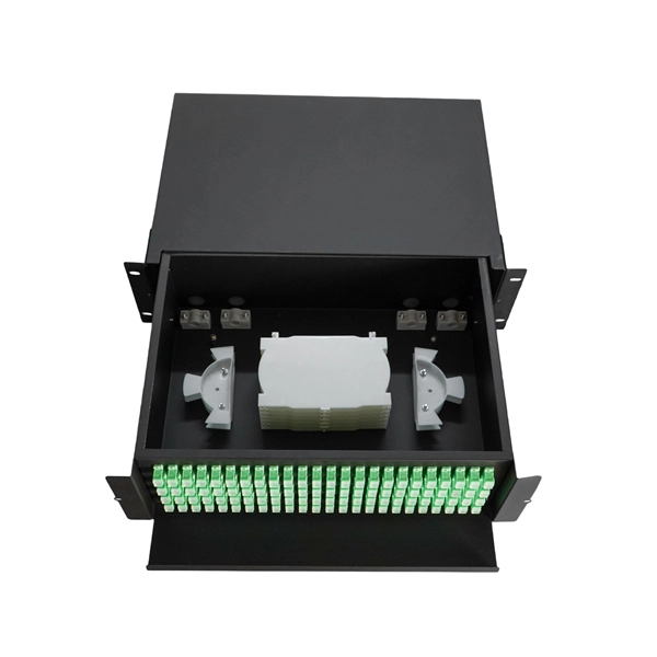
Learn how to splice fiber optic cable using fusion splicing with this complete step-by-step guide. Includes tools, best practices, loss standards (ITU-T G. 652), cost analysis, and FAQs for network engineers and installers. Field-terminating connectors is a meticulous, high-pressure process where even a tiny mistake can force you to cut the fiber and start all over again. This is exactly why most professional installers have moved away from field-termination and toward splicing. Regardless of the type of fiber network you're deploying, be it for telecom, enterprise data centers, or smart city infrastructure, fusion splicing provides the benefits of. Executive Summary: A fiber optic pigtail is one of the most commonly specified yet least understood components in structured cabling. When Do You Need to Splice Fiber Optic Cables? Fiber optic cable splicing. Think of a fiber optic cable splice as the seamless stitching that keeps data flowing through the delicate threads of a network—like a master tailor joining fabric with precision. Remove the outer coating carefully to expose the fiber. Use alcohol wipes to remove dust and debris.
[PDF Version]
Purchasing and installing pigtails for aluminum wiring typically runs from a few hundred to several thousand dollars, depending on circuit count, wire gauges, and labor. The main cost drivers are material choices, labor time, and the need for anti-oxidation connectors and proper. Homeowners typically pay for copper pigtails, connector kits, and skilled labor to replace aluminum wiring with safer copper pigtails. This. Upgrading or installing a residential electrical panel in the San Francisco Bay Area is a significant project that must meet California's stringent safety codes. The price depends on the home size, number of devices, the required materials, and local labor rates. This article presents practical price ranges and the main cost drivers for a typical U S residence.
An is a component with two or more ports that selectively transmits, redirects, or blocks an optical signal in a transmission medium. According to , an optical switch must be actuated to select or change between states. The actuating signal (also referred to as the control signal) is usually electrical, but in principle, could be optical or mechanical. (The control signal format may be Boolean and may be an independent signal; or, in the case of optical actuation, the control signal may.
Three modes, Mode A, Mode B, and 4-pair mode, are available. (In the standard, these are discussed as two Modes, with the term 4-pair mode for both simultaneously.)OverviewPower over Ethernet (PoE) describes any of several or systems that pass along with data on cabling. This allows a single cable to provide both a data connection. There are several common techniques for transmitting power over Ethernet cabling, defined within the broader standard since 2003. The three t. The original PoE standard, IEEE 802.3af-2003, now known as Type 1, provides up to 15.4 W of power (minimum 44 V DC and 350 mA) on each port. Only 12.95 W is guaranteed to be available at the powered device as s.
Contact us for competitive quotes on any of our power communication and smart grid products
Get a Quote